
 EN
EN

 English
  русский
  Français
  Español
  عربى
عربى 
 Get a Quote
Capacitor Discharge Welding Transformer
×
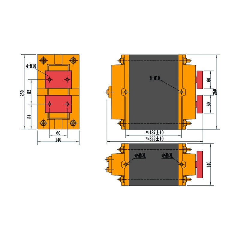
1000J-450V Capacitor Discharge Welding Transformer
| Product Parameters (1000J) | |
| Rated Voltage | 450V |
| NO. of turns | 50 turns |
| Capacitor | 10000UF |
| In the case of the secondary loop 400*300mm, rated voltage and capacitor, the effective value of alternating discharge | 20KA |
| Consumer of cooling water | 2L/min |
| Insulation class | F |
| Protective grade | II |
| Weight | 45KG |
×
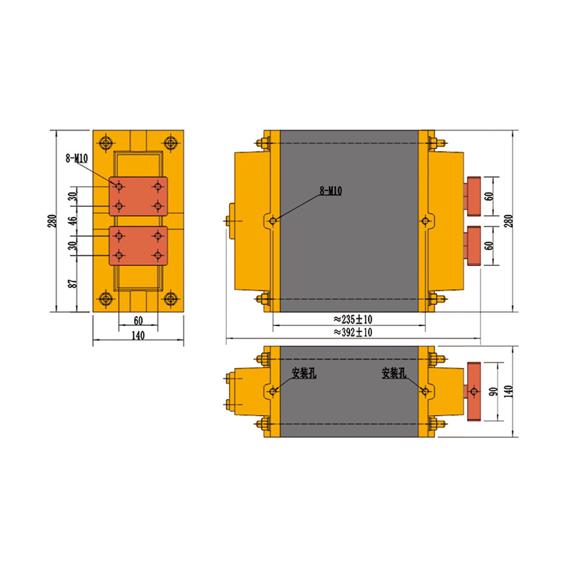
2000J-450V Capacitor Discharge Welding Transformer
| Product Parameters (2000J) | |
| Rated Voltage | 450V |
| NO. of turns | 37 turns |
| Capacitor | 20000UF |
| In the case of the secondary loop 400*300mm, rated voltage and capacitor, the effective value of alternating discharge | 30KA |
| Consumer of cooling water | 3L/min |
| Insulation class | F |
| Protective grade | II |
| Weight | 65KG |
×
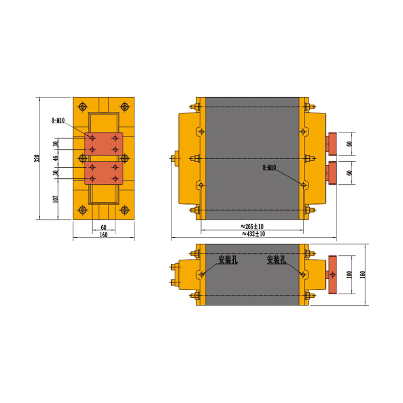
3000J-450V Capacitor Discharge Welding Transformer
| Product Parameters (3000J) | |
| Rated Voltage | 450V |
| NO. of turns | 27 turns |
| Capacitor | 30000UF |
| In the case of the secondary loop 400*300mm, rated voltage and capacitor, the effective value of alternating discharge | 40KA |
| Consumer of cooling water | 3L/min |
| Insulation class | F |
| Protective grade | II |
| Weight | 95KG |
×
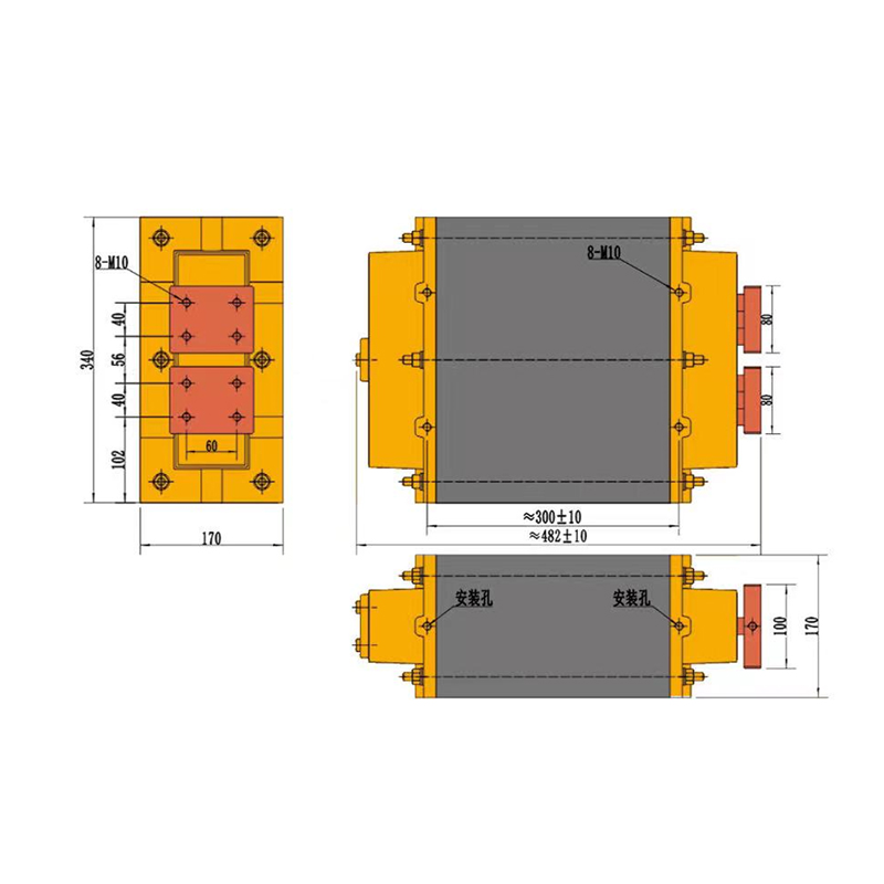
4000J-450V Capacitor Discharge Welding Transformer
| Product Parameters (4000J) | |
| Rated Voltage | 450V |
| NO. of turns | 23 turns |
| Capacitor | 40000UF |
| In the case of the secondary loop 400*300mm, rated voltage and capacitor, the effective value of alternating discharge | 50KA |
| Consumer of cooling water | 4L/min |
| Insulation class | F |
| Protective grade | II |
| Weight | 125KG |
×
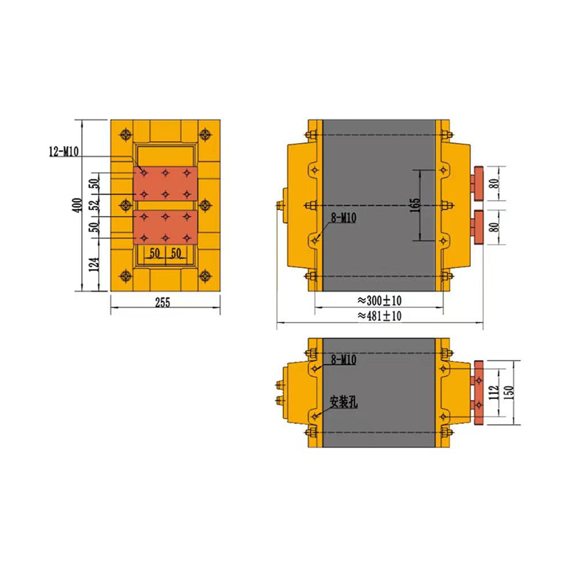
5000J-450V Capacitor Discharge Welding Transformer
| Product Parameters (5000J) | |
| Rated Voltage | 450V |
| NO. of turns | 20 turns |
| Capacitor | 50000UF |
| In the case of the secondary loop 400*300mm, rated voltage and capacitor, the effective value of alternating discharge | 60KA |
| Consumer of cooling water | 5L/min |
| Insulation class | F |
| Protective grade | II |
| Weight | 210KG |
×
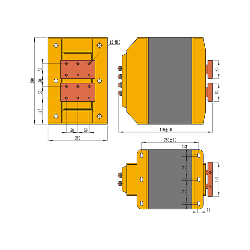
6000J-800V Capacitor Discharge Welding Transformer
| Product Parameters (6000J) | |
| Rated Voltage | 800V |
| NO. of turns | 44/55/66 turns |
| Capacitor | 18000UF |
| In the case of the secondary loop 400*300mm, rated voltage and capacitor, the effective value of alternating discharge | 70KA |
| Consumer of cooling water | 6L/min |
| Insulation class | F |
| Protective grade | II |
| Weight | / |
×
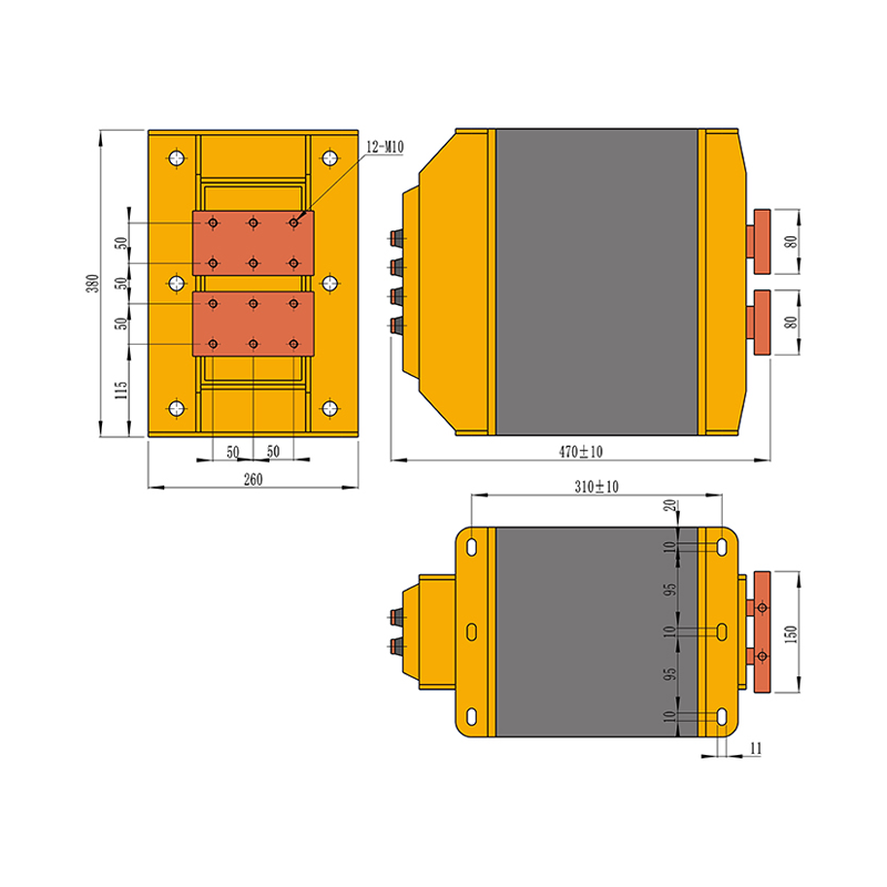
10000J-800V Capacitor Discharge Welding Transformer
| Product Parameters (10000J) | |
| Rated Voltage | 800V |
| NO. of turns | 33/44/55 turns |
| Capacitor | 30000UF |
| In the case of the secondary loop 400*300mm, rated voltage and capacitor, the effective value of alternating discharge | 90KA |
| Consumer of cooling water | 9L/min |
| Insulation class | F |
| Protective grade | II |
| Weight | / |
×
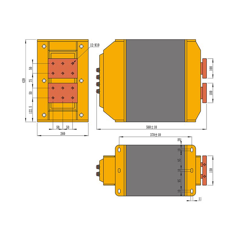
20000J-800V Capacitor Discharge Welding Transformer
| Product Parameters (20000J) | |
| Rated Voltage | 800V |
| NO. of turns | 27/36/45 turns |
| Capacitor | 60000UF |
| In the case of the secondary loop 400*300mm, rated voltage and capacitor, the effective value of alternating discharge | 140KA |
| Consumer of cooling water | 9L/min |
| Insulation class | F |
| Protective grade | II |
| Weight | / |
×
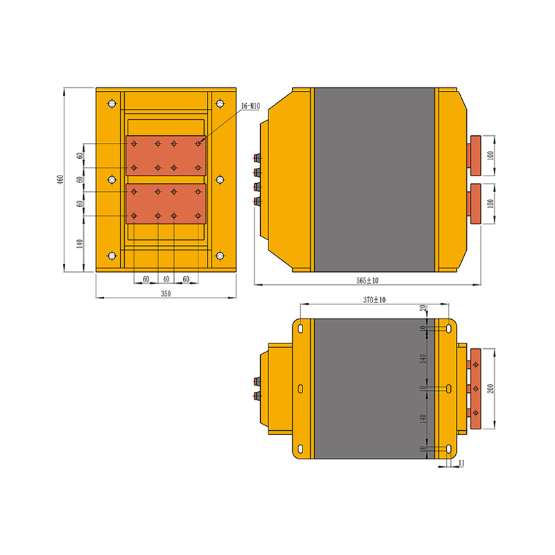
30000J-800V Capacitor Discharge Welding Transformer
| Product Parameters (30000J) | |
| Rated Voltage | 800V |
| NO. of turns | 24/32/40 turns |
| Capacitor | 90000UF |
| In the case of the secondary loop 400*300mm, rated voltage and capacitor, the effective value of alternating discharge | 180KA |
| Consumer of cooling water | 12L/min |
| Insulation class | F |
| Protective grade | II |
| Weight | / |
Capacitor discharge welding transformers store energy in capacitors and release high current in a very short time for spot welding, precision welding, and small parts welding. They are suitable for electronic components, thin materials, battery tabs, and small hardware pieces. The short current release minimizes the heat-affected zone, produces uniform and stable welds, prevents deformation or damage, and enhances production efficiency and weld quality.
About Us
Yongkang Jiaxiao Welding Automation Equipment Co., Ltd.
Since its establishment 30 years ago, Yongkang Jiaxiao Welding Automation Equipment Co., Ltd. has specialized in the research, development, manufacturing, sales, and service of resistance welding machines, specialized welding machines, Durable Welding Machine Transformer, and automated stamping equipment for materials such as copper, aluminum, iron, and stainless steel. The China Welding Machine Transformer supplier boasts a dedicated R&D team led by experts and comprised of diverse engineers. Its products have passed both the Chinese 3C and European CE certifications, and the company holds dozens of national patents. The company is a leading domestic manufacturer of resistance and automatic welding machines.
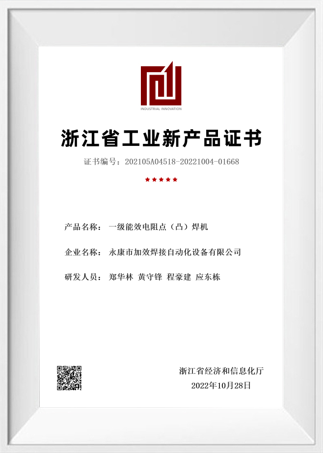
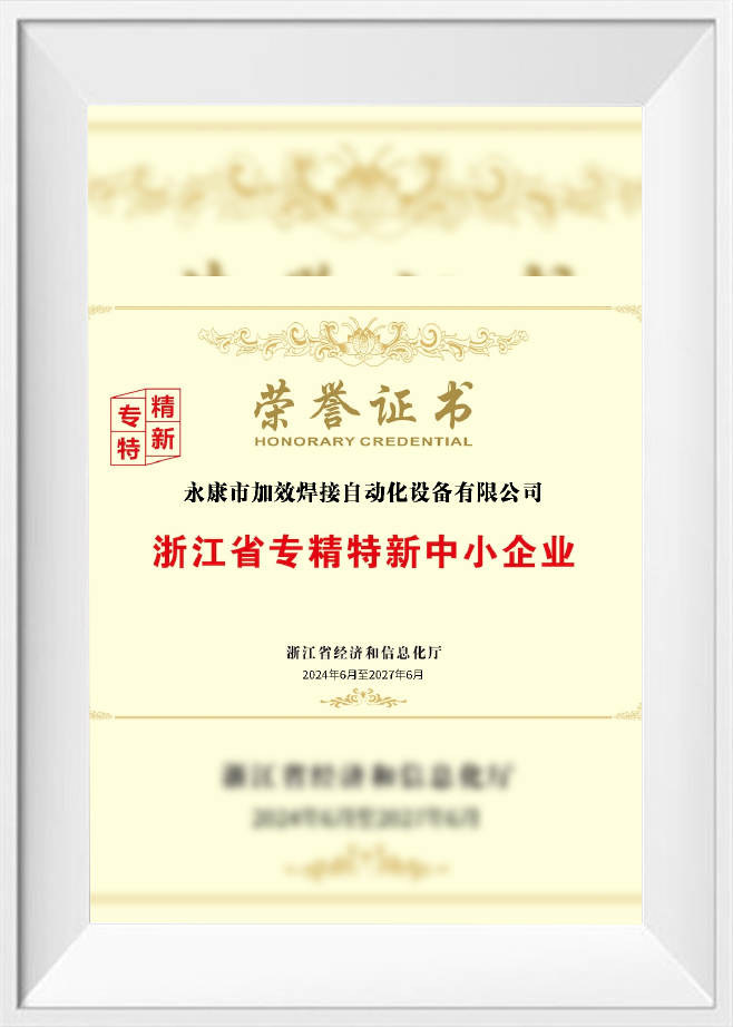
Certificate Of Honour

News
Message Feedback
Capacitor Discharge Welding Transformer for Precision Resistance Welding
A capacitor discharge welding transformer plays a key role inside capacitor discharge spot welding machines and precision resistance welding systems, taking the energy stored up in capacitor banks and turning it into a short burst of high-peak welding current. This lets the machine achieve welds with rapid heat input while keeping thermal spread tightly limited.
You'll typically find this type of transformer paired with thin sheets, plated parts, battery tabs, electronic terminals, small hardware components, metal contacts, automotive electrical parts, and precision metal assemblies. When equipment manufacturers and production plants need to select the right transformer for this application, several factors come into play — energy level, rated voltage, capacitance, winding turns, discharge current, secondary loop size, cooling condition, available installation space, and the weld quality the process demands.
What Is a Capacitor Discharge Welding Transformer?
A capacitor discharge welding transformer, also called a CD welding transformer or capacitive energy storage welding transformer, is designed for welding systems that release stored electrical energy from capacitors in a very short time.
Unlike conventional AC resistance welding transformers, which work directly with industrial power frequency input, a capacitor discharge welding transformer receives a rapid discharge pulse from the capacitor bank. It transforms this pulse into high-current output at the secondary side for welding.
Core Role in Capacitor Discharge Welding Equipment
In a capacitor discharge spot welder, the transformer affects:
- Peak welding current
- Discharge waveform
- Heat input concentration
- Weld nugget formation
- Effective discharge efficiency
- Welding repeatability
- Transformer temperature rise
- Compatibility with the secondary welding loop
Because capacitor discharge welding often works with short pulses, transformer response speed, winding design, secondary circuit loss, and terminal connection quality are critical.
Where Capacitor Discharge Welding Transformers Fit Best
Capacitor discharge welding transformers earn their place wherever welding demands a quick burst of energy, high peak current, and heat input that stays tightly controlled. This makes them a natural fit for thin materials, small components, plated parts, and precision metal assemblies — anything that simply can't afford to deal with excessive thermal deformation.
- Spot Welding When it comes to spot welding, CD transformers step in to deliver short-pulse current that joins thin sheets, conductive parts, small stamped components, and plated metal pieces together. That capability comes in handy for electronic terminals, contacts, small brackets, and precision hardware.
- Projection Welding Projection welding calls for the transformer to focus current right at raised points, bosses, terminals, or contact areas. Because the discharge happens so quickly, heat concentrates precisely at the projection site, which supports stable, consistent joint formation.
- Battery Tab Welding Battery tab welding brings capacitor discharge transformers together with materials like nickel strips, nickel-plated sheets, copper tabs, aluminum tabs, and conductive connectors. Getting the transformer selection right here means factoring in the tab material, thickness, secondary loop size, and how stable the current needs to stay throughout the process.
- Small Part and Thin Sheet Welding These transformers also handle small part and thin sheet welding tasks — stainless steel sheets, galvanized sheets, metal foils, mesh parts, and miniature hardware components all fall into this category. For these applications, keeping the discharge behavior stable and dialing in the right electrode pressure matters a great deal, since both help cut down on spatter, indentation, and heat-affected zones.
Effect of Capacitance and Discharge Current on Welding Results
Capacitance and discharge current sit at the center of how a capacitor discharge welding system performs — they directly shape weld strength, heat input, and the overall range within which welding stays usable. Getting these two right means matching them against material thickness, weld area, electrode pressure, and the transformer's own output characteristics.
More capacitance means more stored energy, while discharge current governs how fast that energy actually reaches the weld point. Get the balance between the two dialed in correctly, and the weld nugget or projection joint tends to form far more consistently. Push the settings too high, though, and you start running into spatter, deep indentation, surface burning, or unwanted deformation.
When it comes to thin foils, small terminals, and plated parts, keeping the energy release under control usually matters more than chasing maximum current. Battery tab welding, in particular, calls for discharge current that stays stable while keeping heat spread around the joint to a minimum. Projection welding takes a different approach — it needs enough peak current to collapse the raised point quickly, and larger weld areas typically demand higher stored energy paired with stronger transformer capacity.
At the end of the day, stable welding comes down to how well capacitance, charging voltage, transformer turns ratio, secondary loop impedance, electrode condition, and welding pressure all work together as a combined system.
CD Transformer vs Power Frequency Transformer vs MFDC Power Source
Capacitor discharge, power frequency, and MFDC systems all belong to resistance welding power solutions, but they deliver energy in different ways. The right choice depends on material type, weld size, heat control requirement, and production method.
| Item | CD Welding Transformer | Power Frequency Transformer | MFDC Power Source |
|---|---|---|---|
| Power principle | Releases stored capacitor energy | Uses 50Hz / 60Hz AC power | Uses inverter-based DC output |
| Output feature | Short high-peak current pulse | AC welding current | Controlled DC welding current |
| Heat input | Fast and concentrated | Based on AC cycles | Precisely regulated |
| Typical applications | Battery tabs, terminals, thin parts | General spot, seam, projection welding | Automated welding and demanding materials |
| System structure | Capacitor bank + discharge circuit | Conventional transformer system | Inverter, rectifier, and controller |
Application Difference
A CD welding transformer is suitable for thin conductive parts, plated components, small terminals, battery tabs, metal contacts, and precision hardware where short heat input is preferred.
A power frequency transformer is commonly used for standard AC spot welding, seam welding, projection welding, and general metal product welding.
An MFDC power source is often selected for automated lines, high-repeatability welding, and applications requiring more refined current control.
How to Select a Capacitor Discharge Welding Transformer
Picking out a capacitor discharge welding transformer really needs to start with the actual welding task at hand, rather than just going by the energy rating stamped on the machine. The transformer has to align with the capacitor bank voltage, stored energy, discharge current demand, welding head structure, and the resistance running through the entire secondary circuit.
When it comes to thin sheets, electronic terminals, and battery tabs, what you want from the transformer is a controlled discharge waveform with current output that stays stable — this goes a long way toward keeping excessive heat from building up around the weld area. Projection welding, or applications involving larger weld areas, calls for a different emphasis entirely: the design here should prioritize peak current capacity, a winding ratio suited to the job, and enough thermal margin to handle repeated discharge cycles without strain.
The secondary circuit itself carries real weight in transformer selection too. Long copper bars, stretched-out electrode arms, undersized conductor sections, or terminal contact that isn't quite up to par can all chip away at the effective current actually reaching the weld point. Whenever these conditions come into play, it makes sense to evaluate the transformer design, terminal structure, and welding loop layout together as a package rather than in isolation.
If you're replacing existing equipment, the new transformer needs to line up with the original rated voltage, energy range, winding turns, installation dimensions, terminal direction, and cooling water layout. Custom welding equipment works a bit differently — here, the transformer typically gets designed around the product material, weld point size, production rhythm, available machine space, and whatever cooling condition the application calls for.
Standard and Custom Capacitor Discharge Welding Transformers
Capacitor discharge welding transformers can be supplied as standard models or customized designs. The right choice depends on energy level, capacitor voltage, discharge waveform, machine layout, and installation requirements.
| Type | Standard CD Welding Transformer | Custom CD Welding Transformer |
|---|---|---|
| Main use | Common CD spot welding machines | Special machines, retrofit projects, automated systems |
| Energy range | Regular ratings such as 1000J–30000J | Matched to specific discharge requirements |
| Rated voltage | Common 450V or 800V systems | Designed for the actual capacitor bank |
| Winding design | Standard turns ratio | Adjusted for target current and waveform |
| Installation | Fixed mounting structure | Adapted to available machine space |
| Terminals | Regular terminal direction | Customized terminal and water port layout |
When to Use a Standard Model
A standard transformer is suitable when the machine’s energy level, rated voltage, mounting size, terminal direction, and cooling layout match regular specifications.
When to Use a Custom Model
A custom transformer is useful when the equipment has special capacitor voltage, limited installation space, unique terminal direction, fixed water inlet and outlet positions, special welding heads, or replacement requirements for an existing transformer.
Why Choose Jiaxiao Capacitor Discharge Welding Transformer
Jiaxiao supplies capacitor discharge welding transformers built for CD spot welding machines, precision resistance welding equipment, battery tab welding systems, small part welders, projection welding machines, and customized automatic welding equipment. These transformers come in configurations that can be matched to common energy levels — 1000J, 2000J, 3000J, 4000J, 5000J, 6000J, 10000J, 20000J, and 30000J — along with rated voltage options of 450V and 800V, depending on how the machine itself is designed.
Whether the need is new machine manufacturing, transformer replacement, ongoing equipment maintenance, or custom welding system integration, Jiaxiao's approach centers on matching stored energy, rated voltage, capacitance, winding turns, discharge current, secondary loop design, water cooling, terminal layout, insulation structure, and installation dimensions to what the actual welding process demands.



 +86-15268688035
 jx12@4006796688.com
 NO.99,Huaxi Road,Chengxi New District,Yongkang city,Zhejiang China.
Message Us Right Now!
Copyright © Yongkang Jiaxiao Welding Automation Equipment Co., Ltd. All Rights
Reserved
China Welding Equipment Manufacturer
