
 EN
EN

 English
  русский
  Français
  Español
  عربى
عربى 
 Get a Quote
Power Frequency Welding Transformer
×
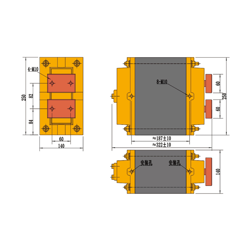
20KVA-3.8V-2 Welding Transformer
| Power source(U1) | 380V |
| Secondary unload voltage(U20) | 3.8V |
| Duty cycle | 20% |
| Power at 10% duty cycle(S10) | 35KVA |
| Power at 20% duty cycle(S20) | 20KVA |
| Power at 100% duty cycle(SP) | 9KVA |
| 100% load current output(IP) | 2400A |
| Maximum short-circuit current for circuits with 500(L)* 300(H)mm | 13.3KA |
| Maximum short-circuit current for circuits with 1000(L)* 300(H)mm | 8.7KA |
| Flow of cooling water Q | 2L/min |
| Insulation class | F |
| Protective grade | II |
| Weight | 45KG |
×
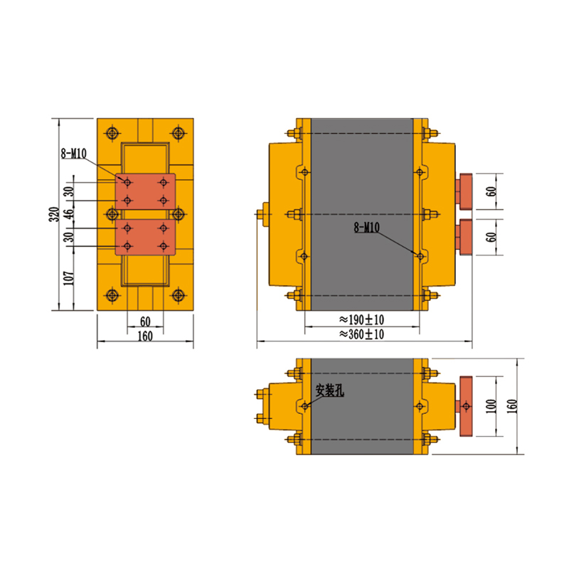
20KVA-3.8V-5 Welding Transformer
| Power source(U1) | 380V |
| Secondary unload voltage(U20) | 3.8V |
| Duty cycle | 20% |
| Power at 10% duty cycle(S10) | 35KVA |
| Power at 20% duty cycle(S20) | 20KVA |
| Power at 100% duty cycle(SP) | 9KVA |
| 100% load current output(IP) | 2400A |
| Maximum short-circuit current for circuits with 500(L)* 300(H)mm | 13.3KA |
| Maximum short-circuit current for circuits with 1000(L)* 300(H)mm | 8.7KA |
| Flow of cooling water Q | 2L/min |
| Insulation class | F |
| Protective grade | II |
| Weight | 45KG |
×
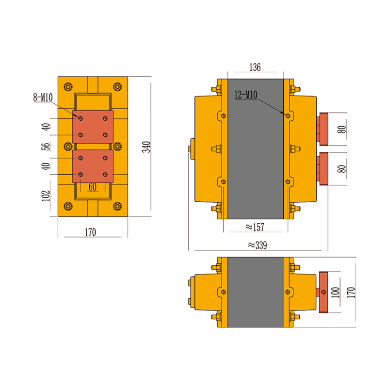
20KVA-3V/3.4V-5 Welding Transformer
| Power source(U1) | 380V |
| Secondary unload voltage(U20) | 3.8V |
| Duty cycle | 50% |
| Power at 20% duty cycle(S10) | 31KVA |
| Power at 50% duty cycle(S20) | 20KVA |
| Power at 100% duty cycle(SP) | 14KVA |
| 100% load current output(IP) | 3800A |
| Maximum short-circuit current for circuits with 500(L)* 300(H)mm | 13.3KA |
| Maximum short-circuit current for circuits with 1000(L)* 300(H)mm | 8.7KA |
| Flow of cooling water Q | 3L/min |
| Insulation class | F |
| Protective grade | II |
| Weight | 60KG |
×
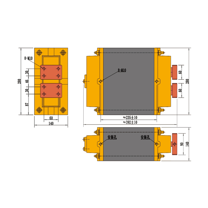
35KVA-5.2V-2 Welding Transformer
| Power source(U1) | 380V |
| Secondary unload voltage(U20) | 5.2V |
| Duty cycle | 20% |
| Power at 10% duty cycle(S10) | 52KVA |
| Power at 20% duty cycle(S20) | 35KVA |
| Power at 100% duty cycle(SP) | 16KVA |
| 100% load current output(IP) | 3000A |
| Maximum short-circuit current for circuits with 500(L)* 300(H)mm | 17.4KA |
| Maximum short-circuit current for circuits with 1000(L)* 300(H)mm | 11.4KA |
| Flow of cooling water Q | 3L/min |
| Insulation class | F |
| Protective grade | II |
| Weight | 65KG |
×
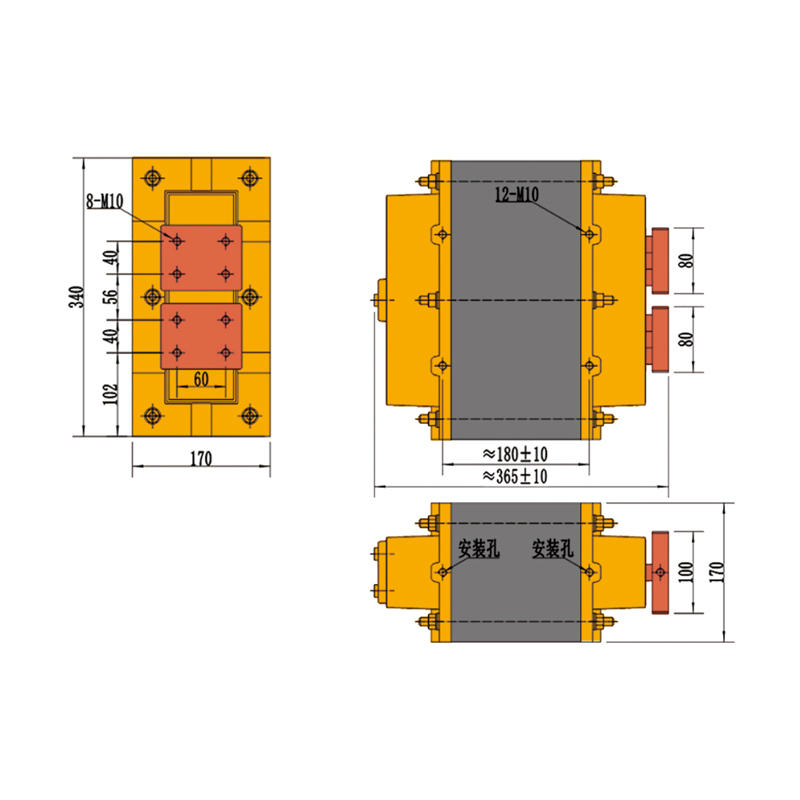
35KVA-5.2V-5 Welding Transformer
| Power source(U1) | 380V |
| Secondary unload voltage(U20) | 5.2V |
| Duty cycle | 50% |
| Power at 20% duty cycle(S10) | 55KVA |
| Power at 50% duty cycle(S20) | 35KVA |
| Power at 100% duty cycle(SP) | 25KVA |
| 100% load current output(IP) | 4800A |
| Maximum short-circuit current for circuits with 500(L)* 300(H)mm | 17.4KA |
| Maximum short-circuit current for circuits with 1000(L)* 300(H)mm | 11.4KA |
| Flow of cooling water Q | 3L/min |
| Insulation class | F |
| Protective grade | II |
| Weight | 75KG |
×
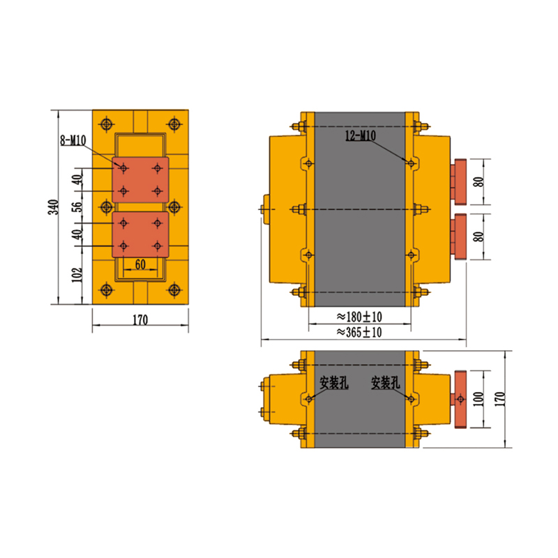
35KVA-4.2V/4.7V-5 Welding Transformer
| Power source voltage (U1) | 380V |
| Secondary no-load voltage (U20) | 4.2V/4.7V |
| Power at 20% duty cycle (S10) | 55KVA |
| Power at 50% duty cycle (S20) | 35KVA |
| Power at 100% duty cycle (SP) | 25KVA |
| 100% load output current (IP) | 5900A |
| Cooling fluid flow rate Q | 4L/min |
| Insulation class | F |
| Protection grade | Class II |
| Weight | 80KG |
×
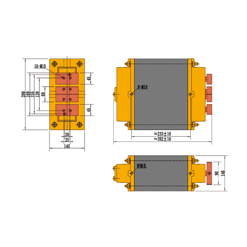
35KVA-10.4V-2 Welding Transformer
| Power source voltage (U1) | 380V |
| Secondary no-load voltage (U20) | 10.4V |
| Power at 10% duty cycle (S10) | 51KVA |
| Power at 20% duty cycle (S20) | 35KVA |
| Power at 100% duty cycle (SP) | 16KVA |
| 100% load output current (IP) | 1500A |
| Maximum short-circuit current for 500mm(L) × 300mm(H) circuit | 9KA |
| Maximum short-circuit current for 1000mm(L) × 300mm(H) circuit | 6KA |
| Cooling fluid flow rate Q | 3L/min |
| Insulation class | F |
| Protection grade | Class II |
| Weight | 65KG |
×
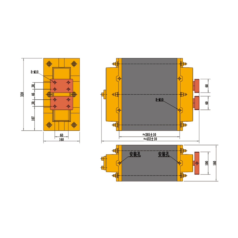
63KVA-7.2V-2 Welding Transformer
| Power source(U1) | 380V |
| Secondary unload voltage(U20) | 7.2V |
| Duty cycle | 20% |
| Power at 10% duty cycle(S10) | 100KVA |
| Power at 20% duty cycle(S20) | 63KVA |
| Power at 100% duty cycle(SP) | 28KVA |
| 100% load current output(IP) | 3900A |
| Maximum short-circuit current for circuits with 500(L)* 300(H)mm | 23.5KA |
| Maximum short-circuit current for circuits with 1000(L)* 300(H)mm | 15.6KA |
| Flow of cooling water Q | 3L/min |
| Insulation class | F |
| Protective grade | II |
| Weight | 95KG |
×
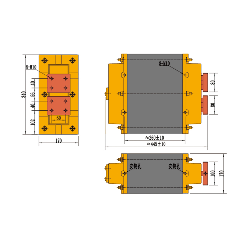
63KVA-7.2V-5 Welding Transformer
| Power source(U1) | 380V |
| Secondary unload voltage(U20) | 7.2V |
| Duty cycle | 50% |
| Power at 20% duty cycle(S10) | 100KVA |
| Power at 50% duty cycle(S20) | 63KVA |
| Power at 100% duty cycle(SP) | 28KVA |
| 100% load current output(IP) | 3900A |
| Maximum short-circuit current for circuits with 500(L)* 300(H)mm | 23.5KA |
| Maximum short-circuit current for circuits with 1000(L)* 300(H)mm | 15.6KA |
| Flow of cooling water Q | 4L/min |
| Insulation class | F |
| Protective grade | II |
| Weight | 110KG |
×
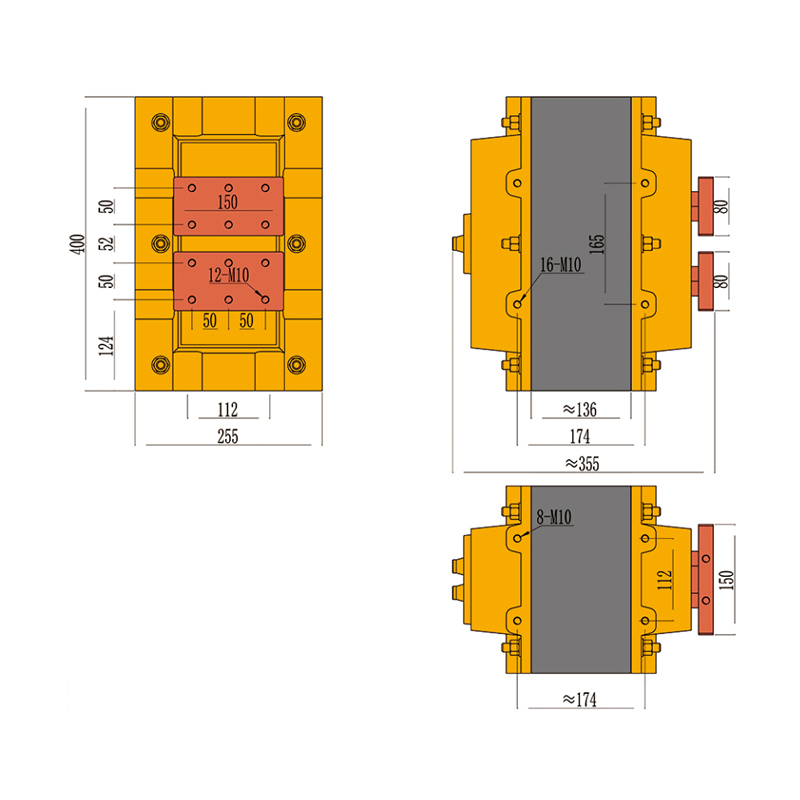
63KVA-4.2V/4.7/5.4V-5 Welding Transformer
| Power source voltage (U1) | 380V |
| Secondary no-load voltage (U20) | 4.2V/4.7V/5.4V |
| Power at 20% duty cycle (S10) | 100KVA |
| Power at 50% duty cycle (S20) | 63KVA |
| Power at 100% duty cycle (SP) | 45KVA |
| 100% load output current (IP) | 10600A |
| Cooling fluid flow rate Q | 5L/min |
| Insulation class | F |
| Protection grade | Class II |
| Weight | 120KG |
×
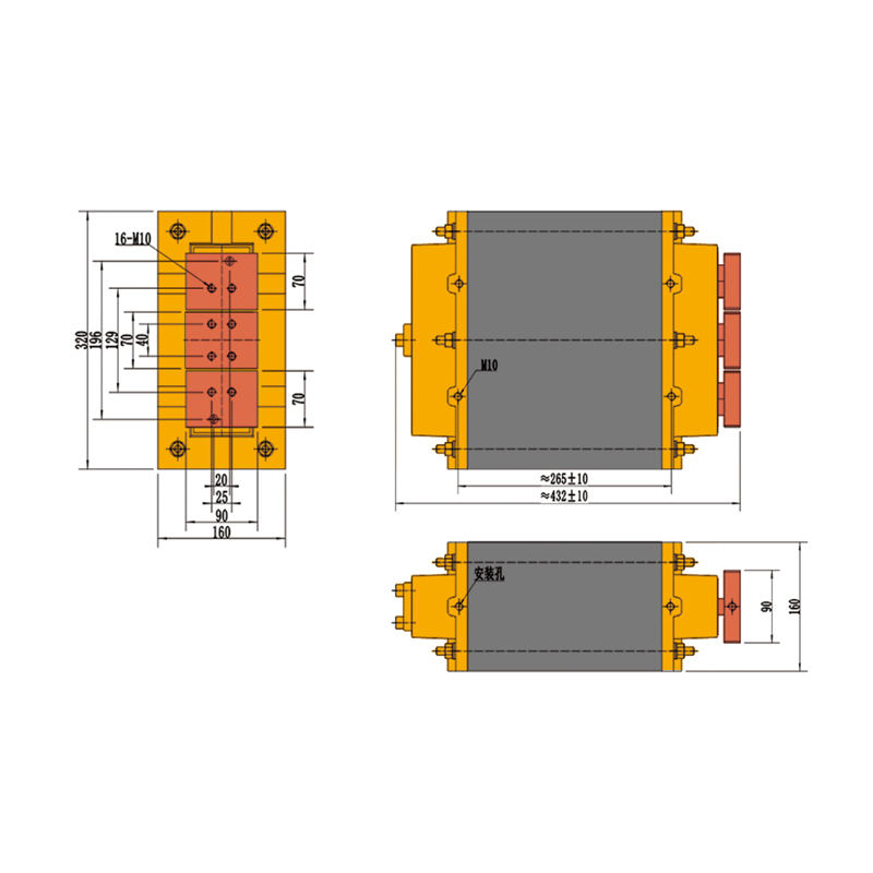
63KVA-14.4V-2 Welding Transformer
| Power source voltage (U1) | 380V |
| Secondary no-load voltage (U20) | 14.4V |
| Power at 10% duty cycle (S10) | 100KVA |
| Power at 20% duty cycle (S20) | 63KVA |
| Power at 100% duty cycle (SP) | 28KVA |
| 100% load output current (IP) | 1900A |
| Maximum short-circuit current for 500mm(L) × 300mm(H) circuit | 11.8KA |
| Maximum short-circuit current for 1000mm(L) × 300mm(H) circuit | 7.8KA |
| Cooling fluid flow rate Q | 3L/min |
| Insulation class | F |
| Protection grade | Class II |
| Weight | 95KG |
×
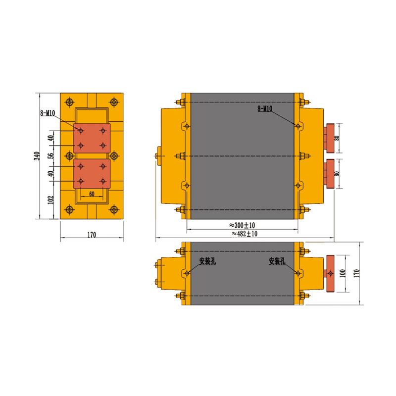
100KVA-8.5V-2 Welding Transformer
| Power source(U1) | 380V |
| Secondary unload voltage(U20) | 8.5V |
| Duty cycle | 20% |
| Power at 10% duty cycle(S10) | 150KVA |
| Power at 20% duty cycle(S20) | 100KVA |
| Power at 100% duty cycle(SP) | 45KVA |
| 100% load current output(IP) | 5300A |
| Maximum short-circuit current for circuits with 500(L)* 300(H)mm | 30KA |
| Maximum short-circuit current for circuits with 1000(L)* 300(H)mm | 20KA |
| Flow of cooling water Q | 4L/min |
| Insulation class | F |
| Protective grade | II |
| Weight | 125KG |
Power frequency welding transformers operate with 50Hz or 60Hz power, lowering voltage and increasing current for metal welding. They are characterized by a simple structure, ease of maintenance, and cost-effectiveness, making them ideal for conventional welding processes and large-scale steel fabrication. They provide stable welding current, ensuring strong and reliable weld joints, and can adapt to various welding environments and conditions.
About Us
Yongkang Jiaxiao Welding Automation Equipment Co., Ltd.
Since its establishment 30 years ago, Yongkang Jiaxiao Welding Automation Equipment Co., Ltd. has specialized in the research, development, manufacturing, sales, and service of resistance welding machines, specialized welding machines, AC Welding Transformer, and automated stamping equipment for materials such as copper, aluminum, iron, and stainless steel. The wholesale Power Frequency Welding Transformer factory boasts a dedicated R&D team led by experts and comprised of diverse engineers. Its products have passed both the Chinese 3C and European CE certifications, and the company holds dozens of national patents. The company is a leading domestic manufacturer of resistance and automatic welding machines.
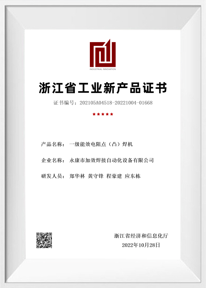
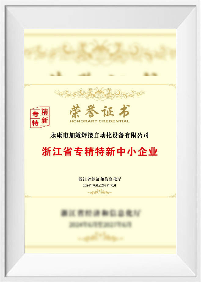
Certificate Of Honour

News
Message Feedback
Power Frequency Welding Transformer for AC Resistance Welding Equipment
A power frequency welding transformer is a core power component used in AC resistance welding equipment. It converts industrial input power at 50Hz or 60Hz into low-voltage, high-current output for spot welding, seam welding, projection welding, multi-point welding, and customized automatic welding systems.
For resistance welding machine manufacturers, equipment maintenance teams, production plants, and automation integrators, transformer selection is not only about KVA capacity. Practical welding performance depends on input voltage, secondary no-load voltage, duty cycle, short-circuit current, welding loop size, copper bar length, electrode arm length, cooling water flow, terminal connection quality, insulation structure, and installation dimensions.
What Is a Power Frequency Welding Transformer?
A power frequency welding transformer is a transformer designed for resistance welding equipment operating directly from standard industrial power frequency, typically 50Hz or 60Hz. It is widely used in conventional AC resistance welding machines because of its mature structure, practical maintenance, and compatibility with many industrial welding applications.
Core Role in AC Resistance Welding Machines
In an AC resistance welding system, the transformer performs the power conversion needed for welding. It changes relatively high input voltage into low secondary voltage and high current. This high current passes through the welding electrodes, copper conductors, and workpiece contact area, generating resistance heat for metal joining.
The transformer affects:
- Welding current capacity
- Heat input range
- Weld nugget formation
- Welding stability
- Duty capability
- Temperature rise
- Energy transfer efficiency
- Machine reliability during repeated operation
In practical equipment design, the transformer must match the welding controller, electrode structure, pressure system, welding loop, cooling system, and workpiece material.
How a Power Frequency Welding Transformer Works
A power frequency welding transformer works through electromagnetic induction. The primary winding receives 50Hz or 60Hz input power. The iron core transfers magnetic energy to the secondary winding, where low-voltage and high-current output is generated.
From Input Voltage to Low-Voltage High-Current Output
Resistance welding requires high current rather than high voltage. The transformer reduces voltage and increases current according to the winding ratio and magnetic core design.
A typical power frequency welding transformer is designed to provide:
- Low secondary voltage
- High welding current
- Short-time overload capability
- Stable output under repeated welding cycles
- Mechanical compatibility with welding machine structures
The output current is used to heat the workpiece interface. The heat generated during resistance welding is mainly influenced by current, contact resistance, and welding time.
Why 50Hz / 60Hz Matters
Power frequency transformers are built around the input frequency. A transformer designed for 50Hz should not be applied to 60Hz or vice versa without technical confirmation, because frequency affects magnetic flux, temperature rise, noise, and transformer performance.
Before selection, confirm:
- Factory input voltage
- Power frequency
- Phase condition
- Welding machine control method
- Transformer wiring structure
- Cooling condition
Applications in Resistance Welding Equipment
Power frequency welding transformers show up across a wide range of AC resistance welding setups, and getting the structure and output right depends on the welding method involved, the current required, throat depth, duty cycle, and how the machine itself is laid out.
Spot Welding Machines
With spot welding equipment, the transformer's job is to deliver high current straight to the electrodes, joining overlapping metal parts in the process. This setup shows up frequently across carbon steel sheets, stainless steel sheets, galvanized sheets, stamped parts, appliance panels, brackets, and wire products.
Seam Welding Machines
Seam welding machines rely on the transformer to push current through rotating wheel electrodes instead. Since seam welding tends to involve longer weld paths along with repeated current cycling, cooling capacity and duty cycle become especially important when selecting the right transformer. You'll typically find this method used on tanks, filters, containers, tube seams, and cylindrical sheet metal parts.
Projection Welding Machines
Projection welding calls for current to concentrate right at raised contact points — think nuts, studs, bosses, or embossed projections. For this to work properly, the transformer needs to supply enough short-time current to keep projection collapse stable and support solid joint formation.
Multi-Point Welding Machines
Depending on how many weld points are involved and how they're arranged, multi-point welding systems might run on a single transformer or several working together. When selecting a transformer for this kind of setup, current distribution, welding sequence, and overall thermal load all need to factor into the decision.
Customized Automatic Welding Systems
Custom automated welding equipment calls for a transformer that's matched precisely to the product structure, fixture design, welding cycle, and the installation space actually available. These systems often get integrated with AC welding controllers, PLC systems, pneumatic or servo pressing units, automatic feeding mechanisms, indexing tables, conveyors, and safety protection structures.
Common Specifications and Secondary Voltage Options
Power frequency welding transformers come in a range of standard KVA ratings, paired with different secondary no-load voltage configurations to suit varying production needs. Picking the right combination comes down to factors like welding machine type, material thickness, loop impedance, and the current level your process actually requires.
Common KVA Ratings
Standard specifications you'll typically come across include:
- 20KVA power frequency welding transformer
- 35KVA power frequency welding transformer
- 63KVA power frequency welding transformer
- Higher-power customized models, built according to specific machine design requirements
Common Secondary No-Load Voltage Options
Secondary no-load voltage typically falls into one of these ranges:
- 3V
- 3.4V
- 3.8V
- 4.2V
- 4.7V
- 5.2V
- 7.2V
- 10.4V
Which voltage level makes sense depends on a combination of factors — material thickness, the size of the welding loop, current demand, and how the machine itself is built. Going with a higher secondary voltage can help push through greater loop impedance, but this needs to be matched thoughtfully. Get it wrong, and you risk excess heat buildup or process behavior that doesn't quite fit the application.
Key Technical Parameters Explained
Knowing what each transformer parameter actually represents makes it much easier to judge whether a unit will genuinely work with your welding machine and fit into your production process.
- Input Voltage The primary side of the transformer draws its power from the input voltage, so this figure needs to line up with both the factory's electrical supply and the welding machine's own design specs. A few things are usually worth double-checking here:
- Voltage level
- Phase
- Frequency
- Wiring method
- Power supply capacity
- Secondary No-Load Voltage This is what you'd measure at the secondary output with no welding load in the circuit. The reading matters because it shapes both the welding current available and how effectively current gets pushed through the welding loop.
- Duty Cycle Duty cycle tells you the amount of load a transformer can sustain over a given time span before its thermal limit kicks in. On automatic welding lines, seam welding equipment, or any setup running across multiple shifts, this number carries real weight.
- 100% Duty Output Current This spec points to the current a transformer can deliver on an ongoing basis, given a specific cooling method and set of operating conditions. It's worth paying attention to when the application calls for continuous or high-frequency welding.
- Maximum Short-Circuit Current You get this figure by shorting the secondary circuit under controlled test conditions, and it gives a general sense of the transformer's capacity. Actual welding current, though, still comes down to the complete welding loop rather than this number alone.
- Water Cooling Flow The flow rate of the cooling water directly impacts temperature rise and how well the transformer holds up under continuous operation. When water flow falls short, overheating, insulation aging, and inconsistent output tend to follow.
- Insulation Grade F Grade F insulation indicates the thermal resistance rating of the materials inside the transformer. You'll find it widely used in industrial resistance welding transformers, given how often these units face repeated thermal cycling.
- Protection Grade Class II Class II protection is tied to how the transformer handles insulation and electrical safety classification. It's still important to verify the actual protective structure against your machine's design and the relevant equipment standards.
- Weight and Installation Dimensions Beyond the obvious, weight and dimensions influence machine frame design, how feasible a replacement will be, maintenance handling, and mounting structure overall. On replacement projects especially, take a close look at mounting hole distance and terminal direction before committing.
Power Frequency Welding Transformer vs MFDC Welding Power Source
Power frequency welding transformers and medium frequency inverter DC welding power sources are both used in resistance welding, but they differ in power conversion method, output characteristics, control precision, and application suitability.
| Item | Power Frequency Welding Transformer | MFDC Welding Power Source |
|---|---|---|
| Input basis | 50Hz or 60Hz industrial power | Inverter-based medium frequency power |
| Output type | AC secondary output | Rectified DC output |
| Structure | Mature and relatively simple | More electronic control components |
| Control response | Suitable for conventional AC welding | Faster current control response |
| Transformer size | Usually larger at similar power | Often more compact |
| Typical use | General spot, seam, projection welding | High-consistency welding, automation, difficult materials |
| Maintenance style | Familiar for many service teams | Requires inverter and controller expertise |
When Power Frequency Transformers Are Suitable
Power frequency transformers are commonly selected for:
- Conventional AC spot welding machines
- AC seam welding machines
- Projection welding machines
- General sheet metal welding
- Hardware welding
- Equipment replacement
- Cost-sensitive machine configurations
- Maintenance-friendly systems
When MFDC May Be Considered
MFDC systems may be considered when the process requires faster current control, reduced current fluctuation, compact transformer size, or high automation compatibility. The choice should be based on material, weld quality requirement, production rhythm, and equipment budget.
Standard vs Custom Power Frequency Welding Transformers
Standard and custom transformers serve different needs. The correct choice depends on machine design, installation space, and process requirements.
| Item | Standard Power Frequency Transformer | Custom Power Frequency Transformer |
|---|---|---|
| Design basis | Common welding machine specifications | Specific equipment and process requirements |
| KVA range | Standard models such as 20KVA, 35KVA, 63KVA | Customized according to current demand |
| Secondary voltage | Common voltage options | Special voltage can be designed |
| Installation size | Fixed dimensions | Adapted to machine frame |
| Terminal layout | Standard direction | Customized terminal position |
| Cooling layout | Standard water channel arrangement | Water inlet and outlet can be adapted |
| Application | General AC resistance welders | Special machines, replacement, automation systems |
When to Choose a Standard Model
A standard model may be suitable when:
- Machine structure matches standard dimensions
- Input and secondary voltage match the process
- Terminal layout is compatible
- Duty cycle is within normal range
- Installation space is sufficient
When to Choose a Custom Model
A custom transformer may be needed when:
- Existing machine dimensions are fixed
- Secondary voltage must be adjusted
- Terminal direction is special
- Water inlet and outlet positions are limited
- Duty cycle is higher than standard use
- The machine has long arms or a large welding loop
- Replacement requires matching an old transformer structure
Jiaxiao's product line covers power frequency welding transformers built for AC resistance welding equipment — spot welding machines, seam welding machines, projection welding machines, multi-point welding systems, and customized automatic welding equipment all fall within scope. Standard configurations span 20KVA, 35KVA, and 63KVA, with higher-power custom models available on request, and secondary voltage can be set at 3V, 3.4V, 3.8V, 4.2V, 4.7V, 5.2V, 7.2V, or 10.4V depending on what the welding job calls for.
New machine manufacturing, equipment maintenance, transformer replacement, custom welding system integration — no matter which of these applies, Jiaxiao's approach stays grounded in matching transformer parameters to real-world welding conditions rather than working off generic specs. That evaluation process draws on input voltage, power frequency, secondary no-load voltage, KVA capacity, output current, duty cycle, welding loop size, copper bar layout, electrode arm length, cooling water flow, insulation grade, terminal direction, and installation dimensions.



 +86-15268688035
 jx12@4006796688.com
 NO.99,Huaxi Road,Chengxi New District,Yongkang city,Zhejiang China.
Message Us Right Now!
Copyright © Yongkang Jiaxiao Welding Automation Equipment Co., Ltd. All Rights
Reserved
China Welding Equipment Manufacturer
