
 EN

 English
 русский
 Français
 Español
 عربى

 Get a Quote
How Are Industrial Pneumatic Cylinders Used in Welding Workstations
Date:Oct 02, 2026
Welding workstations involve more than the welding operation itself. Before a part can be worked on, it may need to be moved into position, held against a fixture, released, and prepared for the next operation. These repeated movements are often handled by pneumatic equipment because compressed air can provide straightforward linear motion without adding a complicated drive arrangement to every fixture.
An Industrial Pneumatic Cylinder can be connected to a clamp, fixture, pressing mechanism, or positioning device to carry out these movements. The rod extends, makes contact with the connected component, and retracts when the holding or positioning task is finished. In a production environment, the same movement may take place again and again, so the way the cylinder is installed and controlled matters as much as its basic ability to move.
A welding workstation also places practical demands on the surrounding equipment. The fixture needs to stay in the intended position, the clamping movement should not disturb the workpiece, and the cylinder should return without unnecessary impact. Air supply, load direction, alignment, and maintenance all become part of the operating picture.
What Roles Do Pneumatic Cylinders Play in Welding Workstations
The role of a pneumatic cylinder is usually easier to see when looking at the fixture rather than the cylinder itself. A cylinder may sit behind a clamp, underneath a positioning mechanism, or beside a fixture and provide the movement needed to bring one component toward another.
For example, a clamp can remain open while a workpiece is placed in the fixture. Once the workpiece is ready, the cylinder extends and moves the clamp into position. After the welding operation, the cylinder retracts and creates space for removal or repositioning.
Similar movements can be used for:
- Holding a workpiece against a fixture
- Moving a clamp into or away from the work area
- Pressing a component into a fixed position
- Moving a fixture between two positions
- Releasing a workpiece after the operation
The cylinder is only one part of this arrangement. The fixture determines how the movement reaches the workpiece, while guides, brackets, and connecting components keep the movement on the intended path.
| Welding workstation task | Typical cylinder action | Main consideration |
|---|---|---|
| Workpiece clamping | Rod extends | Contact and holding force |
| Clamp release | Rod retracts | Clear return movement |
| Fixture positioning | Extension or retraction | Repeatable travel |
| Pressing | Controlled extension | Load and movement resistance |
| Fixture movement | Repeated linear travel | Alignment and smooth operation |
This division of responsibilities is useful when looking at cylinder performance. A problem that appears to be caused by the pneumatic cylinder may actually come from the fixture or the way the moving parts are connected.
How Do Pneumatic Cylinders Support Workpiece Clamping and Positioning
Clamping is one of the more direct uses of pneumatic movement in a welding workstation. The cylinder does not usually touch the workpiece itself. Instead, its rod moves a clamp or another mechanical component that makes contact with the part.
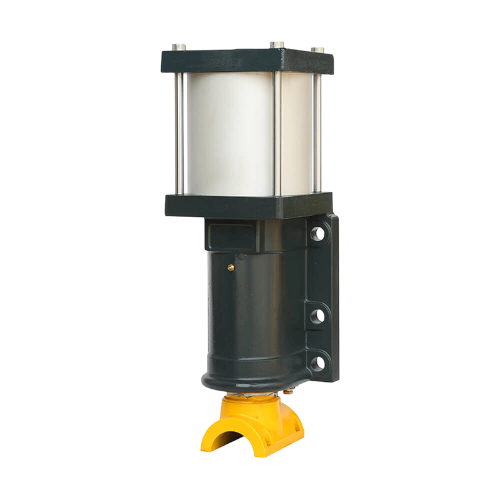
The arrangement has to allow the clamp to approach the workpiece without pushing it out of position. If the contact point is poorly located, the workpiece can shift as the clamp closes. That can create problems even when the cylinder itself is moving normally.
Positioning and clamping also need to be treated as separate mechanical functions. A clamp can hold a part, but it should not necessarily be responsible for guiding the entire fixture. Where the moving assembly needs additional support, a separate guide can handle that task while the Industrial Pneumatic Cylinder supplies the linear force.
A typical movement may look simple:
- The workpiece is placed in the fixture.
- The cylinder moves the clamp toward the part.
- The clamp reaches its holding position.
- The workpiece remains supported during the operation.
- The cylinder retracts and releases the clamp.
The arrangement becomes less straightforward when the workpiece has an uneven surface or when the clamp approaches from an angle. In those cases, the fixture design and contact geometry have a direct effect on how well the pneumatic movement works.
How Does Cylinder Force Affect Welding Workstation Operations
A cylinder needs enough force to move the connected mechanism and hold the intended load. That does not mean a larger cylinder should simply be selected whenever more force is available.
The useful force at the fixture can change with the way the cylinder is mounted. A direct connection produces a different mechanical result from a linkage or lever arrangement. The direction of the load matters too. A cylinder moving horizontally does not face the same conditions as one supporting a vertical fixture.
For clamping work, the required force is related to the resistance created by the fixture and the workpiece. The contact arrangement also matters. If the clamp is positioned far from the supporting point, the mechanism may require more force than a simple look at the workpiece weight would suggest.
A practical selection process therefore looks at the complete movement:
- What is being moved?
- Where is the load located?
- In which direction does the cylinder move?
- How much resistance does the fixture create?
- Is the cylinder connected directly or through another mechanism?
- Does the fixture require separate guiding support?
The same Industrial Pneumatic Cylinder can behave differently when installed in two different mechanisms. This is why cylinder force should be considered together with the mechanical layout instead of treated as a standalone specification.
There is also a difference between moving a part and holding it. The force required during movement may not be identical to the force needed once the fixture reaches its working position.
How Does Air Flow Control Pneumatic Cylinder Movement
A welding fixture does not always need the cylinder to move at the same speed from beginning to end. A clamp may approach the workpiece relatively quickly and then need a more controlled final movement. After release, the return stroke may follow another movement pattern.
Air flow has a direct influence on how quickly the cylinder moves. Restrictions in the air path can slow the rod, while a less restricted flow path allows the movement to take place more quickly. The load on the fixture changes the result as well.
This is where movement adjustment becomes useful. A cylinder that moves too quickly can cause the fixture to strike its stopping point or contact the workpiece abruptly. A cylinder that moves too slowly can hold up the workstation sequence.
It is also worth looking at extension and retraction separately. The two directions may have different loads, different mechanical resistance, and different air-flow behavior. Adjusting one side of the movement does not necessarily produce the same result on the other.
| Observed movement | What may be happening | What to inspect |
|---|---|---|
| Clamp approaches too quickly | Air flow is not sufficiently restricted | Flow adjustment |
| Movement slows under load | Load or resistance is increasing | Fixture and air supply |
| Extension is smooth but return is slow | Return path has greater resistance | Tubing and connections |
| Movement changes during operation | Air supply may be fluctuating | Supply and connected equipment |
| Motion feels uneven | Mechanical resistance may vary | Alignment and fixture movement |
For an Industrial Pneumatic Cylinder used in a repeated welding operation, movement control is not only about achieving a particular speed. The transition between movement, contact, holding, and release also needs to suit the fixture.
Why Is Cylinder Alignment Important for Welding Fixtures
A pneumatic cylinder works most naturally when its rod moves along the same general direction as the load. Problems begin when the connected fixture pushes sideways against the rod or when the mounting points are not properly aligned.
Side loading can increase friction around the moving parts. The rod may also experience forces that were not intended to be carried by the cylinder. With repeated operation, these conditions can contribute to wear around the rod and sealing areas.
The fixture should therefore have its own support wherever the mechanical design requires it. A guide can keep the moving assembly on track while the cylinder provides the pushing or pulling action.
Installation checks are relatively straightforward. The cylinder should move freely before it is connected to the full load. The fixture should also travel through its intended path without binding. If resistance appears before the pneumatic connection is made, increasing air pressure is not a real solution to the underlying mechanical problem.
Alignment is especially relevant in welding workstations because fixtures often repeat the same movement. A small offset may not be obvious during an initial check but can become a recurring source of resistance during normal operation.
The connection between the cylinder rod and fixture deserves attention as well. A rigid connection may transfer unwanted side forces if the two components do not share the same movement path. The mounting arrangement needs to allow the fixture to move as intended without forcing the cylinder to compensate for mechanical misalignment.
How Does Cushioning Affect Pneumatic Cylinder Movement
A moving cylinder assembly has to slow down before it reaches the end of its stroke. If the movement continues at the same pace until the mechanical stop, the resulting impact can be felt through the fixture and mounting structure.
Cushioning provides a way to control this final part of the stroke. It is particularly relevant when the cylinder operates a clamp or positioning mechanism that moves repeatedly between fixed positions.
The adjustment is not simply a matter of making the cylinder stop as softly as possible. Too much cushioning can cause the movement to slow earlier than required. Too little cushioning can leave a noticeable impact at the end of travel.
The load connected to the rod also changes the behavior. A light fixture and a heavier fixture can produce different end-of-stroke movement even when the same cylinder is used. Movement speed matters in the same way.
For welding fixtures, the final approach is often more important than the middle portion of the stroke. Once the clamp gets close to the workpiece, an abrupt movement can affect the fixture, the contact surface, or the position of the part.
This makes cushioning part of the overall movement arrangement rather than an isolated setting. It works alongside air-flow adjustment, mechanical alignment, and the load carried by the fixture.
How Does Compressed Air Quality Affect Cylinder Operation
The air supply has a direct connection with pneumatic equipment performance. Moisture and contaminants can travel through the air line and eventually reach the cylinder and other connected components.
A small amount of contamination may not immediately stop the equipment, but it can affect moving and sealing surfaces over time. Moisture can also create problems elsewhere in the pneumatic circuit.
Air preparation equipment helps address these conditions before the air reaches the actuator. Filters, drains, tubing, fittings, and connections all have a role in keeping the air path in suitable condition.
Pressure stability is another part of the picture. A cylinder may appear to operate normally when working alone but behave differently when several pneumatic devices use the same supply. A drop in available pressure can change movement and holding force.
For a welding workstation, routine checks can include:
- Inspecting air lines for damage
- Checking connections for leakage
- Removing accumulated moisture where required
- Checking the condition of filtration equipment
- Observing whether cylinder movement changes when other pneumatic equipment operates
These observations can help separate a cylinder problem from an air-supply problem. In a busy workstation, that distinction can save time during troubleshooting because the visible symptom is not always located at the source of the problem.
How Can Pneumatic Cylinder Maintenance Support Reliable Welding Operations
Maintenance is easier when changes in cylinder behavior are noticed early. A clamp that begins moving more slowly, a rod that shows unusual wear, or a fixture that no longer reaches its normal position can provide useful signs during routine inspection.
The cylinder should not be inspected by itself. The complete movement path deserves attention. A fixture may become harder to move because of mechanical interference, while a cylinder may appear weak because of an air leak farther upstream.
A useful inspection path is:
Air supply → connections → tubing → cylinder → mounting points → fixture → contact point
Following the movement in this order makes it easier to locate where the change begins.
External leakage around fittings should be checked, along with the condition of the rod and visible sealing areas. Mounting hardware should also remain secure, particularly where the cylinder works through repeated extension and retraction.
When a problem is found, the cause should be identified before replacing components. A worn seal may require attention to the cylinder, while uneven movement caused by fixture resistance may require work on the mechanical assembly instead.
For an Industrial Pneumatic Cylinder operating in a welding workstation, maintenance is closely tied to the condition of the complete setup. Air quality, alignment, movement speed, cushioning, load, and fixture condition all influence how the actuator behaves during repeated operation. Keeping these elements in view makes troubleshooting more straightforward and helps maintain the intended movement of the workstation.
Related products
-
-
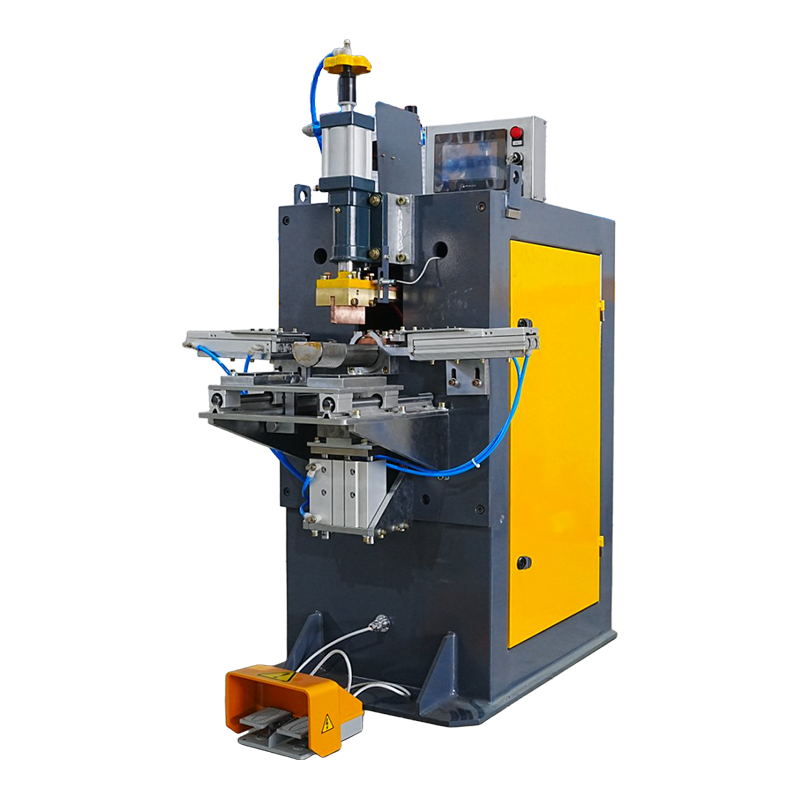
The Welding Machine for Semi-Circular Pen Holder is engineered for precision welding of semi-circular pen holders, integrating high‑accuracy automated positioning and servo control systems to deliver ...
See Details -
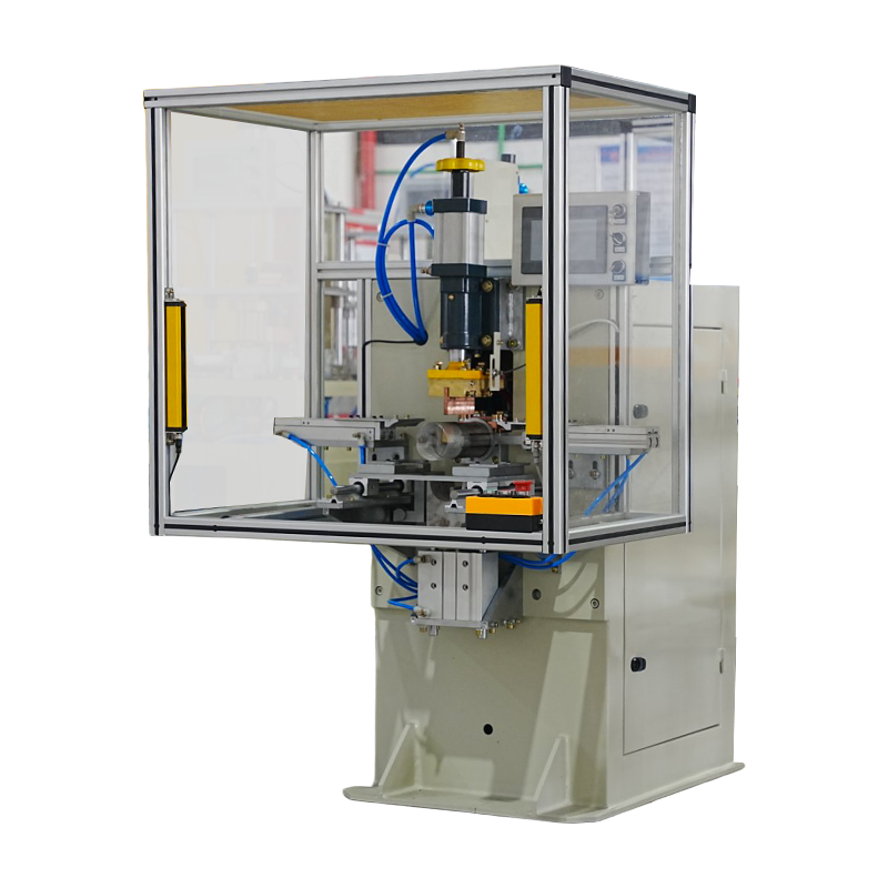
The Roll & Weld Integrated Machine for Pen Holder seamlessly combines rolling and welding in a single automated process. With servo‑driven precision and tailored tooling, this machine transforms f...
See Details -
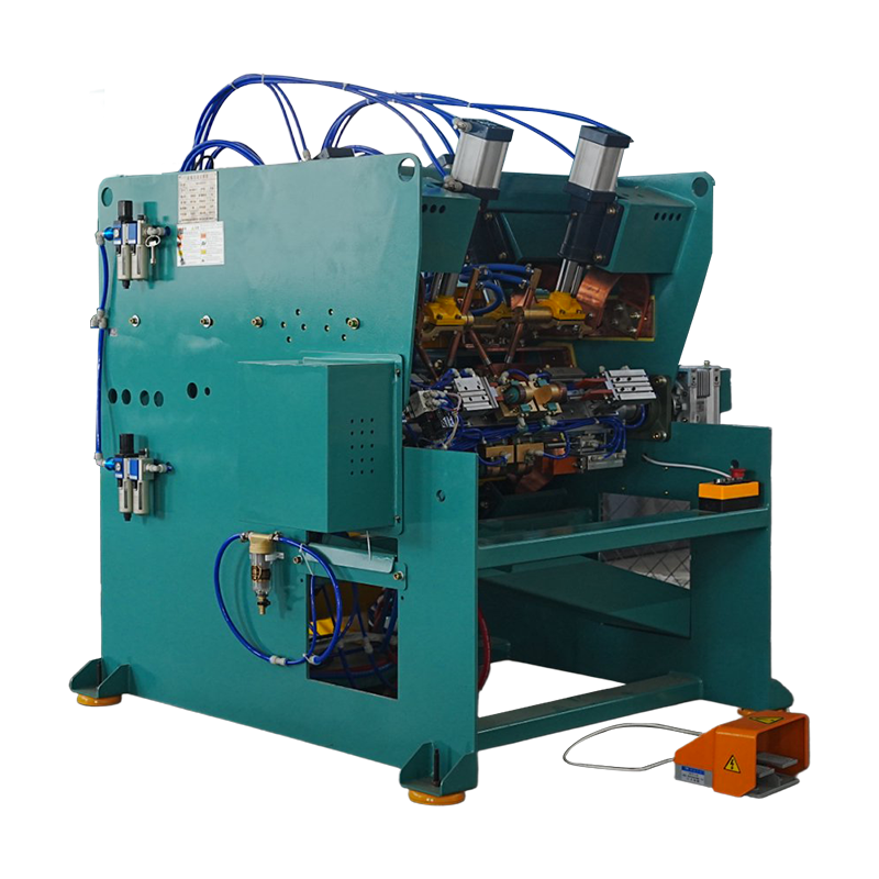
The 3‑Head Automatic Rotary Welding Machine for Hot Glue Gun is engineered for high‑volume welding of plastic or metal components on glue gun assemblies.
See Details -

The 160KVAx2x16 Gantry Frame Resistance Spot Welding Machine is a high-performance automatic welding system engineered for demanding industrial production.
See Details



 +86-15268688035
 jx12@4006796688.com
 NO.99,Huaxi Road,Chengxi New District,Yongkang city,Zhejiang China.
Message Us Right Now!
Copyright © Yongkang Jiaxiao Welding Automation Equipment Co., Ltd. All Rights
Reserved
China Welding Equipment Manufacturer
