
 EN
EN

 English
  русский
  Français
  Español
  عربى
عربى 
 Get a Quote
Welding Transformers
×
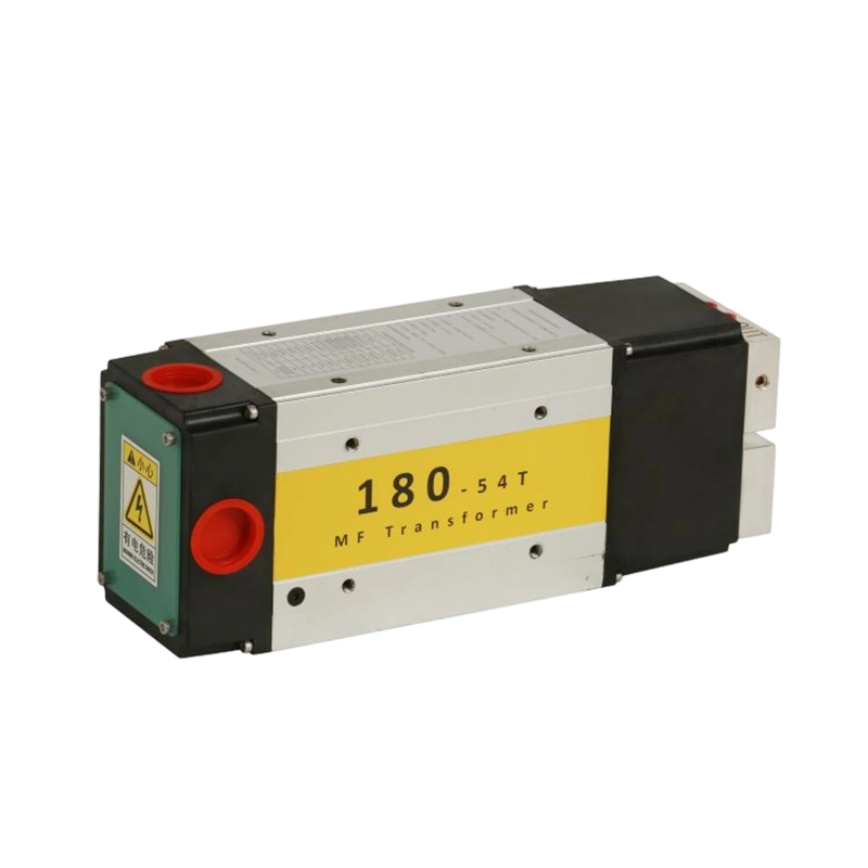
MF180-54T Welding Transformer
| Power source(U1N) | 1000HZ/500V |
| Secondary unload voltage(U20) | 9.3V |
| Power/current at 10% duty cycle(ON 200ms and OFF 1800ms) | 280KVA/30KA |
| Power/current at 20% duty cycle(ON 400ms and OFF 1600ms) | 180KVA/20KA |
| Power/current at 50% duty cycle(ON 1000ms and OFF 1000ms) | 125KVA/13.5KA |
| Power/current at 100% duty cycle | 75KVA/8KA |
| Maximum short-circuit current | 45KA |
| Flow of cooling water Q | ≥2×8L/min |
| Pressure difference of cooling water△P | ≥0.15Mpa |
| Insulation class | H |
| Protective grade | IP30 |
| Weight | 28KG |
| Executive Standard | GB/T25301-2021ISO5826:2014 |
×
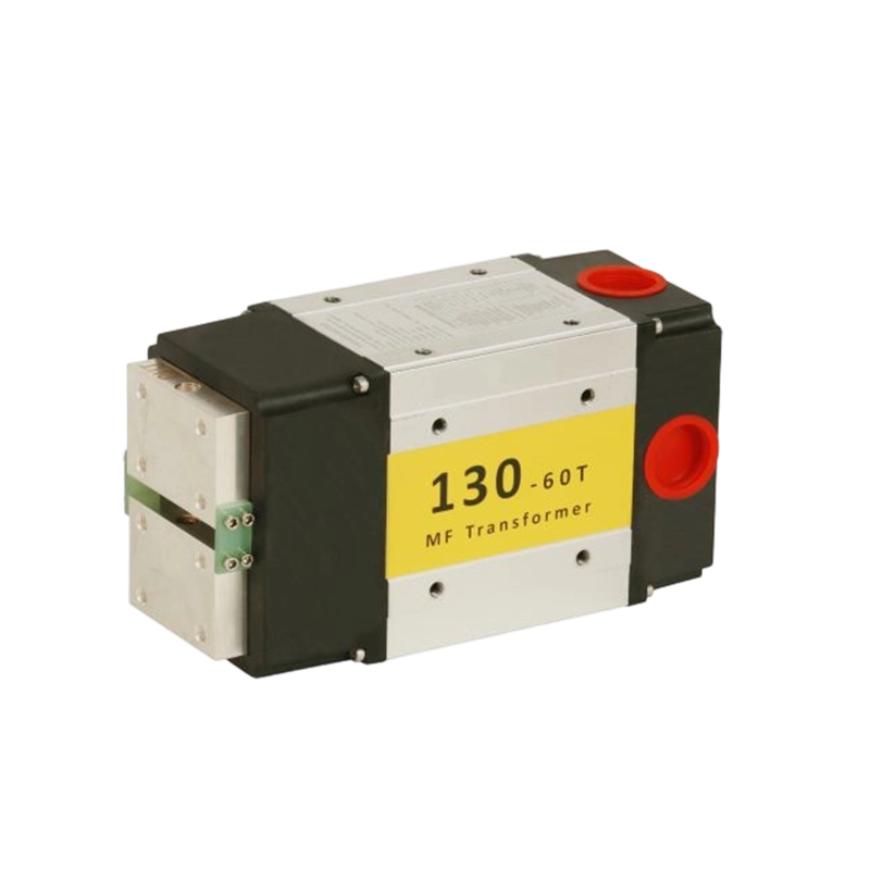
MF130-60T Welding Transformer
| Power source(U1N) | 1000HZ/500V |
| Secondary unload voltage(U20) | 8.3V |
| Power/current at 10% duty cycle(ON 200ms and OFF 1800ms) | 200KVA/24KA |
| Power/current at 20% duty cycle(ON 400ms and OFF 1600ms) | 130KVA/15.6KA |
| Power/current at 50% duty cycle(ON 1000ms and OFF 1000ms) | 80KVA/9.6KA |
| Power/current at 100% duty cycle | 50KVA/6KA |
| Maximum short-circuit current | 38KA |
| Flow of cooling water Q | ≥8L/min |
| Pressure difference of cooling water△P | ≥0.15Mpa |
| Insulation class | H |
| Protective grade | IP30 |
| Weight | 18KG |
| Executive Standard | GB/T25301-2021ISO5826:2014 |
×
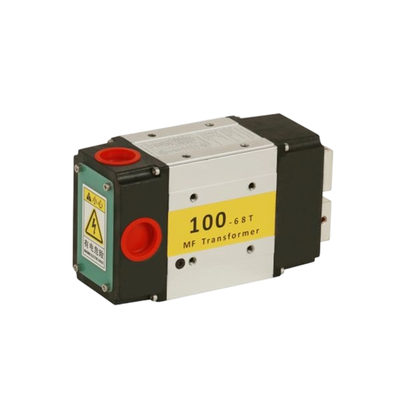
MF100-68T Welding Transformer
| Power source(U1N) | 1000HZ/500V |
| Secondary unload voltage(U20) | 7.2V |
| Power/current at 10% duty cycle(ON 200ms and OFF 1800ms) | 160KVA/22KA |
| Power/current at 20% duty cycle(ON 400ms and OFF 1600ms) | 100KVA/13.6KA |
| Power/current at 50% duty cycle(ON 1000ms and OFF 1000ms) | 63KVA/8.6KA |
| Power/current at 100% duty cycle | 40KVA/5.4KA |
| Maximum short-circuit current | 30KA |
| Flow of cooling water Q | ≥8L/min |
| Pressure difference of cooling water△P | ≥0.15Mpa |
| Insulation class | H |
| Protective grade | IP30 |
| Weight | 12KG |
| Executive Standard | GB/T25301-2021ISO5826:2014 |
×
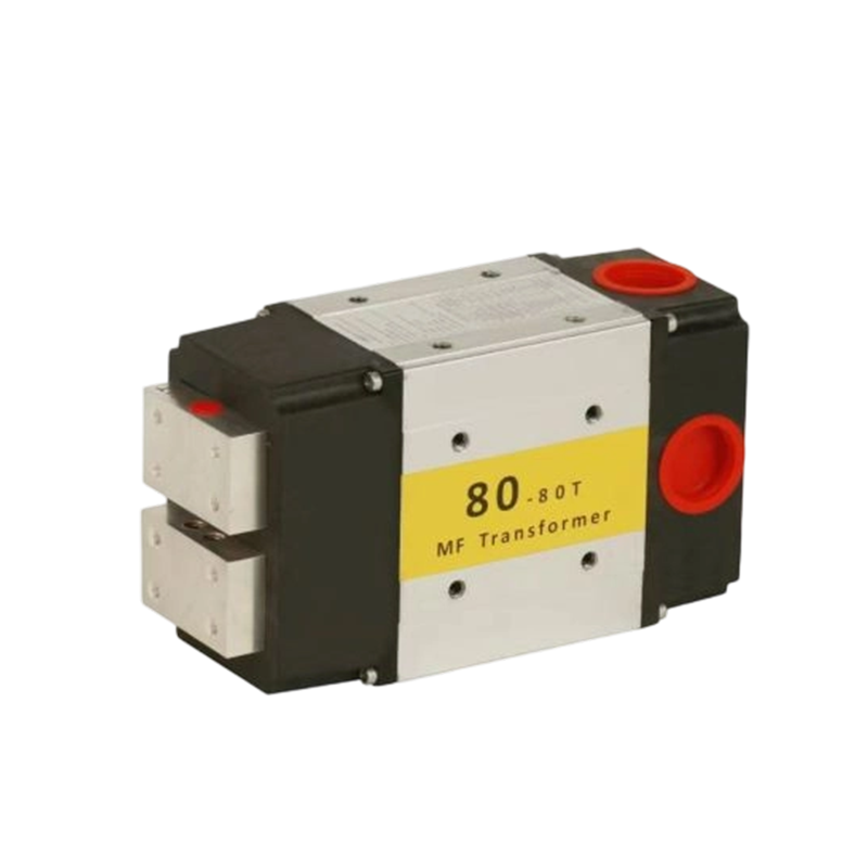
MF80-80T Welding Transformer
| Power source(U1N) | 1000HZ/500V |
| Secondary unload voltage(U20) | 6.3V |
| Power/current at 10% duty cycle(ON 200ms and OFF 1800ms) | 130KVA/20.5KA |
| Power/current at 20% duty cycle(ON 400ms and OFF 1600ms) | 80KVA/12.8KA |
| Power/current at 50% duty cycle(ON 1000ms and OFF 1000ms) | 50KVA/8KA |
| Power/current at 100% duty cycle | 32KVA/5KA |
| Maximum short-circuit current | 28KA |
| Flow of cooling water Q | ≥8L/min |
| Pressure difference of cooling water△P | ≥0.15Mpa |
| Insulation class | H |
| Protective grade | IP30 |
| Weight | 12KG |
| Executive Standard | GB/T25301-2021ISO5826:2014 |
×
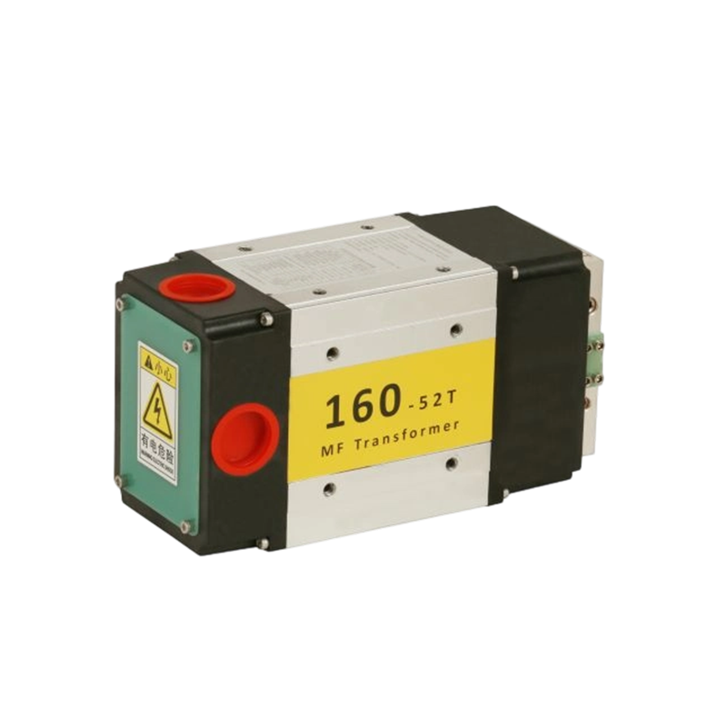
MF160-52T Welding Transformer
| Power source(U1N) | 1000HZ/500V |
| Secondary unload voltage(U20) | 9.6V |
| Power/current at 10% duty cycle(ON 200ms and OFF 1800ms) | 250KVA/26KA |
| Power/current at 20% duty cycle(ON 400ms and OFF 1600ms) | 160KVA/16.6KA |
| Power/current at 50% duty cycle(ON 1000ms and OFF 1000ms) | 100KVA/10.4KA |
| Power/current at 100% duty cycle | 63KVA/6.5KA |
| Maximum short-circuit current | 40KA |
| Flow of cooling water Q | ≥8L/min |
| Pressure difference of cooling water△P | ≥0.15Mpa |
| Insulation class | H |
| Protective grade | IP30 |
| Weight | 18.5KG |
| Executive Standard | GB/T25301-2021ISO5826:2014 |
×
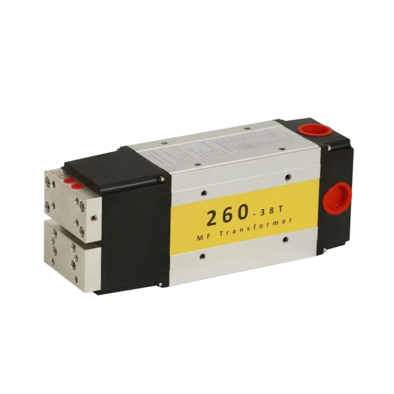
MF260-38T Welding Transformer
| Power source(U1N) | 1000HZ/500V |
| Secondary unload voltage(U20) | 13.2V |
| Power/current at 10% duty cycle(ON 200ms and OFF 1800ms) | 400KVA/30KA |
| Power/current at 20% duty cycle(ON 400ms and OFF 1600ms) | 260KVA/20KA |
| Power/current at 50% duty cycle(ON 1000ms and OFF 1000ms) | 180KVA/13.7KA |
| Power/current at 100% duty cycle | 106KVA/8KA |
| Maximum short-circuit current | 55KA |
| Flow of cooling water Q | ≥2×8L/min |
| Pressure difference of cooling water△P | ≥0.15Mpa |
| Insulation class | H |
| Protective grade | IP30 |
| Weight | 30KG |
| Executive Standard | GB/T25301-2021ISO5826:2014 |
×
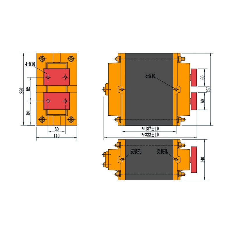
1000J-450V Capacitor Discharge Welding Transformer
| Product Parameters (1000J) | |
| Rated Voltage | 450V |
| NO. of turns | 50 turns |
| Capacitor | 10000UF |
| In the case of the secondary loop 400*300mm, rated voltage and capacitor, the effective value of alternating discharge | 20KA |
| Consumer of cooling water | 2L/min |
| Insulation class | F |
| Protective grade | II |
| Weight | 45KG |
×
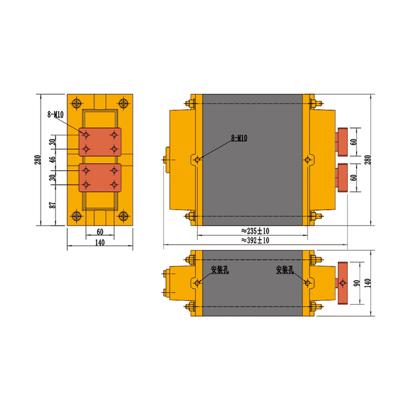
2000J-450V Capacitor Discharge Welding Transformer
| Product Parameters (2000J) | |
| Rated Voltage | 450V |
| NO. of turns | 37 turns |
| Capacitor | 20000UF |
| In the case of the secondary loop 400*300mm, rated voltage and capacitor, the effective value of alternating discharge | 30KA |
| Consumer of cooling water | 3L/min |
| Insulation class | F |
| Protective grade | II |
| Weight | 65KG |
×
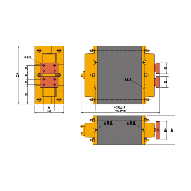
3000J-450V Capacitor Discharge Welding Transformer
| Product Parameters (3000J) | |
| Rated Voltage | 450V |
| NO. of turns | 27 turns |
| Capacitor | 30000UF |
| In the case of the secondary loop 400*300mm, rated voltage and capacitor, the effective value of alternating discharge | 40KA |
| Consumer of cooling water | 3L/min |
| Insulation class | F |
| Protective grade | II |
| Weight | 95KG |
×
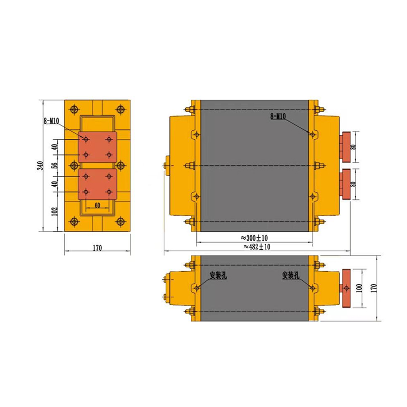
4000J-450V Capacitor Discharge Welding Transformer
| Product Parameters (4000J) | |
| Rated Voltage | 450V |
| NO. of turns | 23 turns |
| Capacitor | 40000UF |
| In the case of the secondary loop 400*300mm, rated voltage and capacitor, the effective value of alternating discharge | 50KA |
| Consumer of cooling water | 4L/min |
| Insulation class | F |
| Protective grade | II |
| Weight | 125KG |
×
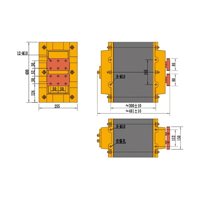
5000J-450V Capacitor Discharge Welding Transformer
| Product Parameters (5000J) | |
| Rated Voltage | 450V |
| NO. of turns | 20 turns |
| Capacitor | 50000UF |
| In the case of the secondary loop 400*300mm, rated voltage and capacitor, the effective value of alternating discharge | 60KA |
| Consumer of cooling water | 5L/min |
| Insulation class | F |
| Protective grade | II |
| Weight | 210KG |
×
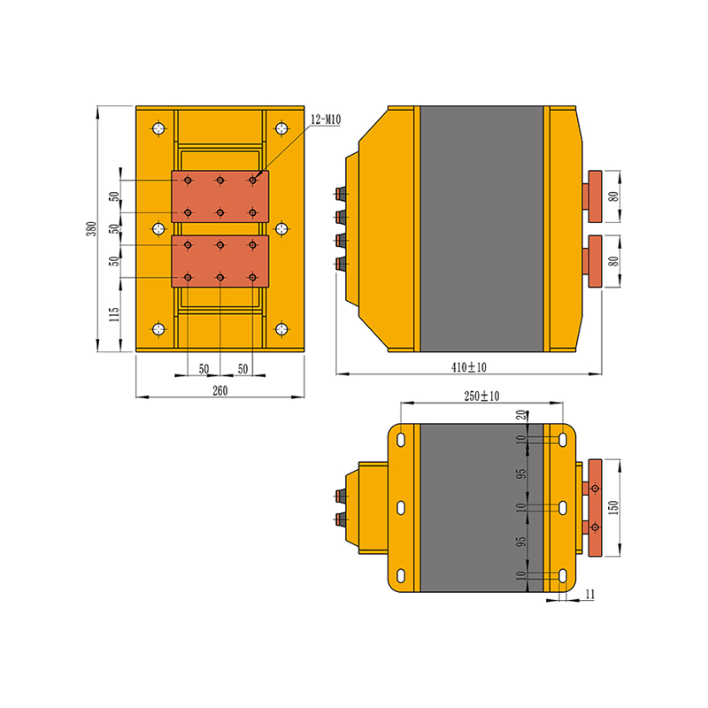
6000J-800V Capacitor Discharge Welding Transformer
| Product Parameters (6000J) | |
| Rated Voltage | 800V |
| NO. of turns | 44/55/66 turns |
| Capacitor | 18000UF |
| In the case of the secondary loop 400*300mm, rated voltage and capacitor, the effective value of alternating discharge | 70KA |
| Consumer of cooling water | 6L/min |
| Insulation class | F |
| Protective grade | II |
| Weight | / |
Welding transformers are essential components of welding equipment, converting high-voltage, low-current power into low-voltage, high-current output suitable for various welding applications. Different types of welding transformers provide specific current waveforms, welding efficiency, and thermal control capabilities to meet diverse industrial needs. They are widely used in steel structure fabrication, automotive manufacturing, electronics assembly, and battery production. High-performance welding transformers ensure consistent weld quality, extend equipment lifespan, and improve overall production efficiency.
About Us
Yongkang Jiaxiao Welding Automation Equipment Co., Ltd.
Since its establishment 30 years ago, Yongkang Jiaxiao Welding Automation Equipment Co., Ltd. has specialized in the research, development, manufacturing, sales, and service of resistance welding machines, specialized welding machines, Resistance Welding Transformer, and automated stamping equipment for materials such as copper, aluminum, iron, and stainless steel. The Spot Welding Transformer factory boasts a dedicated R&D team led by experts and comprised of diverse engineers. Its products have passed both the Chinese 3C and European CE certifications, and the company holds dozens of national patents. The company is a leading domestic manufacturer of resistance and automatic welding machines.
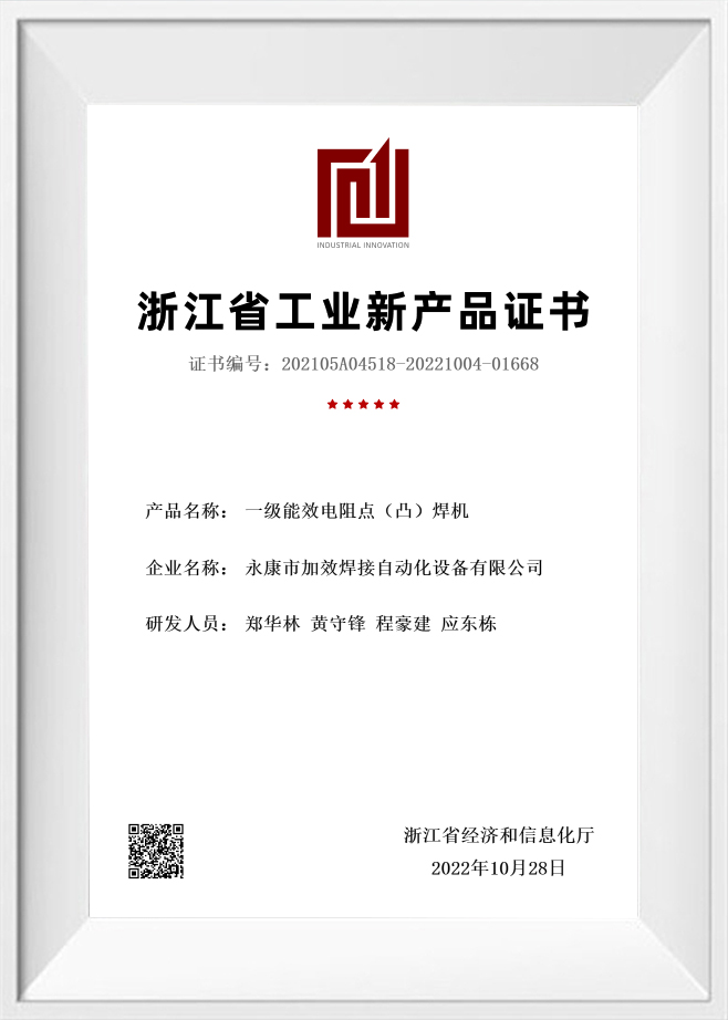
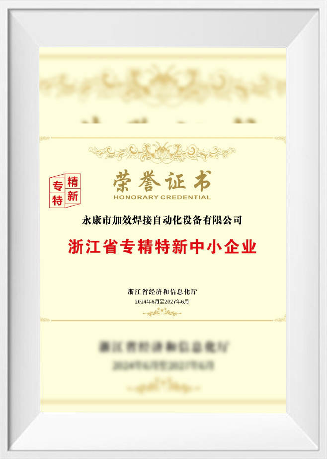
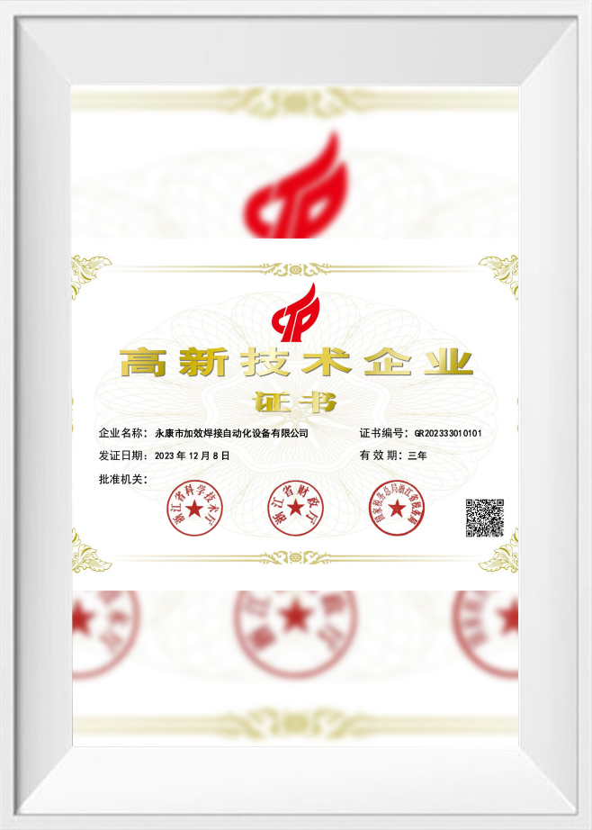
Certificate Of Honour
News
Message Feedback
Welding Transformers for Resistance Welding Equipment
Welding transformers act as the core power conversion component inside resistance welding machines, converting input voltage into low-voltage, high-current output so the equipment can generate resistance heat right at the workpiece contact area. Across spot welding machines, seam welding machines, projection welding machines, multi-point welding machines, and customized automated welding systems, the transformer plays a direct role in shaping welding current capacity, heat generation, duty cycle, temperature rise, and long-term operating stability.
For industrial applications, selecting a welding transformer takes more than simply picking a KVA rating. Input voltage, secondary no-load voltage, output current, duty cycle, cooling method, welding loop size, copper bar length, electrode arm length, insulation grade, terminal structure, installation space, and production rhythm all come together to shape the actual welding result.
What Is a Welding Transformer?
A welding transformer is an electrical device designed to change input power into a suitable output for welding. In resistance welding equipment, it usually converts relatively high input voltage into low secondary voltage and very high welding current.
The high current passes through electrodes, copper conductors, and workpieces. Heat is generated at the contact resistance area, forming a weld nugget or welded joint under pressure.
Core Role in Resistance Welding Machines
In resistance welding systems, the welding transformer is responsible for:
- Providing high welding current
- Matching welding power to material thickness
- Supporting stable heat input
- Working with the welding controller
- Adapting to the welding loop design
- Withstanding repeated current cycles
- Supporting continuous or intermittent production
The transformer does not work alone. Its performance must match the machine structure, electrode system, cooling design, welding controller, and production duty requirement.
How a Welding Transformer Converts Voltage into High Current
A welding transformer operates through electromagnetic induction. The primary coil receives input voltage, and the secondary coil outputs lower voltage with much higher current.
Low Voltage and High Current Output
Resistance welding usually requires very high current and relatively low voltage. The transformer reduces voltage and increases current according to its winding design.
In practical resistance welding equipment, the secondary output is used to heat the workpiece interface. The heat generated depends on current, resistance, and welding time.
Important factors include:
- Primary input voltage
- Secondary no-load voltage
- Transformer turns ratio
- Core design
- Copper coil size
- Welding loop impedance
- Electrode contact condition
- Welding time
- Cooling condition
A transformer with suitable output characteristics helps the welding machine deliver enough heat without excessive temperature rise or unstable current behavior.
Applications in Resistance Welding Equipment
Welding transformers show up in a wide range of resistance welding machines and automated welding systems, and the transformer design needs to align with both the welding process and the mechanical structure at hand.
Spot Welding Machines
In spot welding machines, the transformer delivers high current to electrode tips, joining overlapping metal sheets, wires, brackets, and stamped parts.
Common applications include:
- Sheet metal parts
- Automotive brackets
- Appliance components
- Metal cabinets
- Wire products
- Hardware parts
The transformer needs to match sheet thickness, electrode arm length, welding current requirement, and duty cycle.
Seam Welding Machines
In seam welding machines, the transformer feeds current through rotating roller electrodes. Since the welding cycle often runs longer than ordinary spot welding, cooling and duty cycle take on extra importance.
Typical applications include:
- Fuel tanks
- Water tanks
- Metal containers
- Filters
- Stainless steel vessels
- Tube seams
Seam welding transformers tend to need stable output paired with strong water cooling, given the continuous or repeated welding cycles involved.
Projection Welding Machines
Projection welding machines rely on high current to weld nuts, studs, embossed points, brackets, and formed projections. Here, the transformer has to deliver current rapidly and sufficiently for concentrated heating.
Typical applications include:
- Weld nuts
- Weld studs
- Automotive fasteners
- Appliance brackets
- Stamped assemblies
Transformer selection should factor in projection quantity, material thickness, and required weld strength.
Multi-Point Welding Machines
Multi-point welding machines may call for one transformer or several, depending on the weld layout. Selection needs to account for simultaneous welding points, current distribution, and welding sequence.
Common applications include:
- Wire mesh
- Metal frames
- Reinforcement grids
- Automotive assemblies
- Appliance panels
- Custom fixtures
Customized Automatic Welding Machines
For non-standard automated welding equipment, the transformer is typically designed around the product, fixture, welding head, motion system, and production rhythm.
Typical integration points include:
- PLC control
- Welding controller
- Servo positioning
- Automatic feeding
- Multi-station fixtures
- Robot interface
- Cooling circuit
- Safety enclosure
Common Types of Welding Transformers
Different resistance welding processes call for different transformer structures. Picking the right type comes down to matching welding method, output requirement, installation layout, and cooling condition.
- Spot Welding Transformer A spot welding transformer is built for spot welding machines, delivering high current across short welding cycles — a common choice for sheet metal and small metal parts.
- Seam Welding Transformer A seam welding transformer serves seam welding machines, and it generally demands better thermal control since seam welding can involve longer welding time or repeated current pulses.
- Projection Welding Transformer A projection welding transformer supplies current for projection welding, where heat concentrates at raised points, nuts, studs, or formed projections.
- Multi-Point Welding Transformer A multi-point welding transformer supports equipment running multiple welding heads or multiple weld points, whether arranged in a single-transformer or multi-transformer layout.
- AC Welding Transformer An AC welding transformer puts out alternating current on the secondary side. It remains a widely used choice in conventional resistance welding machines, thanks to its mature structure and practical maintenance.
- Water-Cooled Welding Transformer A water-cooled welding transformer relies on cooling water channels to keep temperature rise in check during operation — a good fit for higher-duty welding machines, seam welders, automatic welding lines, and continuous production environments.
- Custom Welding Transformer A custom welding transformer gets built around installation size, input voltage, secondary voltage, output current, duty cycle, terminal direction, water inlet and outlet position, and overall machine structure.
Common Power Specifications
Welding transformers come in both standard and customized power ranges, with 20KVA, 35KVA, 63KVA, and higher-capacity custom types among the most common models.
- 20KVA Welding Transformer A 20KVA welding transformer typically handles small spot welding machines, light-duty resistance welding, thin sheets, wires, and small hardware parts.
- 35KVA Welding Transformer A 35KVA welding transformer fits medium light-duty spot welding, sheet metal parts, appliance components, and small fixtures.
- 63KVA Welding Transformer A 63KVA welding transformer works well for higher-current spot welding, projection welding, and medium-duty industrial resistance welding applications.
- Higher-Power Custom Welding Transformers Higher-power custom transformers get selected for:
- Large spot welding machines
- Seam welding machines
- Projection welding machines
- Multi-point welding equipment
- Automated resistance welding lines
- High-duty production systems
KVA rating should not be judged in isolation — it needs to be weighed together with secondary voltage, duty cycle, welding loop impedance, and cooling design.
Key Technical Parameters Explained
Getting familiar with transformer parameters goes a long way toward avoiding mismatches between the transformer and the welding machine.
- Input Voltage Input voltage is the power supply voltage feeding the primary side of the transformer. Depending on factory location and machine design, industrial systems can run on different voltage standards.
Before making a selection, confirm:- Input voltage
- Phase requirement
- Frequency
- Power supply capacity
- Existing machine electrical layout
- Secondary No-Load Voltage Secondary no-load voltage is what gets measured at the transformer's secondary side without any welding load applied. It shapes available welding current, heat input, and how adaptable the process can be.
A higher secondary voltage can help push more current through a larger welding loop or higher-resistance path, but it still needs to align with the machine design and welding requirement. - Duty Cycle Duty cycle describes how long a transformer can run under load, within a given period, before hitting its thermal limit.
A higher duty cycle matters most for:- Continuous production
- Seam welding
- Automated welding stations
- Multi-shift operation
- High-frequency welding cycles
- 100% Duty Output Current The 100% duty output current shows the current a transformer can supply continuously under specified cooling and operating conditions — a parameter worth close attention when evaluating continuous or high-duty applications.
- Maximum Short-Circuit Current Maximum short-circuit current reflects the current available when the secondary circuit gets shorted under test conditions. It is a handy way to compare transformer capability, though actual welding current still depends on the complete welding loop.
- Water Cooling Flow Water cooling flow influences transformer temperature rise and continuous working capability. The flow rate needed depends on transformer power, duty cycle, cooling channel design, and the operating environment.
- Insulation Grade F Insulation Grade F refers to the heat resistance level of the insulation materials used — a standard commonly found in industrial transformers, where temperature rise needs to stay within safe operating limits.
- Protection Grade Class II Class II protection is a classification tied to electrical insulation and safety design. The actual protection structure should get reviewed against equipment design and the relevant application standards.
- Weight Transformer weight factors into machine installation, mounting plate strength, maintenance handling, and replacement planning. Heavier transformers often call for reinforced mounting structures.
How to Select the Right Welding Transformer
Selecting a welding transformer requires matching electrical output, thermal capacity, mechanical installation, and welding process needs.
Main Selection Factors
Key factors include:
- Welding machine type
- Welding process
- Required KVA power
- Input voltage
- Secondary no-load voltage
- Required welding current
- Duty cycle
- Maximum short-circuit current
- Welding loop size
- Copper bar length
- Electrode arm length
- Cooling method
- Water cooling flow
- Installation space
- Mounting direction
- Terminal layout
- Production rhythm
- Ambient working condition
Practical Selection Guide
| Application Requirement | Recommended Selection Direction |
|---|---|
| Small spot welding machine | 20KVA or similar light-duty transformer |
| Medium sheet metal welding | 35KVA or 63KVA transformer, depending on thickness |
| Projection welding | Higher current output and strong secondary structure |
| Seam welding | Water-cooled transformer with suitable duty cycle |
| Multi-point welding | Transformer selection based on number of weld points and sequence |
| Long electrode arms | Higher consideration for secondary voltage and loop impedance |
| Automated welding line | Higher duty cycle, cooling capacity, and stable terminals |
| Replacement project | Match original dimensions, voltage, current, and mounting structure |
The transformer should be selected based on actual welding current demand and machine structure, not KVA rating alone.
Standard Welding Transformers vs Custom Welding Transformers
Both standard and custom welding transformers are used in resistance welding equipment. The choice depends on installation requirements and process demands.
| Item | Standard Welding Transformer | Custom Welding Transformer |
|---|---|---|
| Design basis | Common machine specifications | Specific machine and process requirements |
| Delivery flexibility | Suitable for regular applications | Designed according to drawings or parameters |
| Installation size | Fixed standard dimensions | Adapted to available space |
| Terminal direction | Standard terminal layout | Customized terminal position |
| Cooling structure | Standard cooling design | Cooling channels can be adapted |
| Application | General spot welding and common machines | Special welders, automation systems, replacement projects |
When to Use a Standard Transformer
A standard transformer may be suitable when:
- Machine structure is common
- Installation space matches standard dimensions
- Output parameters meet the process requirement
- Terminal position is compatible
- Duty cycle is not unusual
When to Use a Custom Transformer
A custom transformer may be needed when:
- Installation space is limited
- Secondary terminal direction is special
- Water inlet and outlet positions must be changed
- Higher duty cycle is required
- Machine uses long arms or large welding loop
- Existing transformer replacement requires matching old structure
- The welding process has special current or voltage needs
Parameters to Confirm When Replacing or Upgrading a Welding Transformer
Getting a replacement project right takes precise matching. Two transformers with the same KVA rating can still turn out to be a poor fit if secondary voltage, mounting size, or terminal layout do not line up.
Electrical Parameters
Confirm:
- Rated KVA
- Input voltage
- Frequency
- Phase
- Secondary no-load voltage
- 100% duty output current
- Maximum short-circuit current
- Duty cycle
- Insulation grade
- Protection classification
Mechanical Parameters
Confirm:
- Overall dimensions
- Mounting hole position
- Mounting direction
- Terminal position
- Terminal size
- Copper bar connection method
- Water inlet and outlet position
- Weight
- Available installation space
Process Parameters
Confirm:
- Welding machine type
- Welding material
- Material thickness
- Required welding current
- Welding cycle
- Production rhythm
- Cooling condition
- Electrode arm length
- Welding loop size
For older machines, photos, nameplate information, terminal drawings, and installation measurements go a long way toward getting the match right.
Why Choose Jiaxiao Welding Transformers
Jiaxiao supplies welding transformers for resistance welding equipment, covering spot welding machines, seam welding machines, projection welding machines, multi-point welding systems, and customized automated welding equipment. Available configurations range from 20KVA, 35KVA, and 63KVA up through higher-power customized models, with options for AC output, water cooling, special terminal layouts, and machine-specific mounting structures.
Whether the project involves new machine manufacturing, equipment maintenance, transformer replacement, or non-standard welding system integration, Jiaxiao keeps the focus on practical parameter matching. Technical evaluation typically covers input voltage, secondary no-load voltage, output current, duty cycle, welding loop size, copper bar layout, cooling flow, insulation grade, terminal direction, and installation dimensions — all working together to fit the transformer to the actual welding process and machine structure.



 +86-15268688035
 jx12@4006796688.com
 NO.99,Huaxi Road,Chengxi New District,Yongkang city,Zhejiang China.
Message Us Right Now!
Copyright © Yongkang Jiaxiao Welding Automation Equipment Co., Ltd. All Rights
Reserved
China Welding Equipment Manufacturer
