
 EN
EN

 English
  русский
  Français
  Español
  عربى
عربى 
 Get a Quote
How Does a Wire Mesh Welding Machine Improve Mesh Production
Date:Aug 28, 2026
Producing welded mesh is not simply a matter of joining two wires at each crossing point. The wires need to arrive at the welding area in the right position, remain stable during movement, and form a regular pattern as production continues. A small change in one part of the process can sometimes show up later as uneven openings, irregular weld points, or a mesh surface that is no longer flat.
For this reason, production conditions deserve attention alongside the equipment itself. Wire diameter, mesh opening, wire tension, welding conditions, material surface, and production speed all have a connection with the finished mesh. When one of these factors changes, the other settings may need to be checked as well.
How Does Wire Diameter Affect a Wire Mesh Welding Machine
Wire diameter has a direct effect on how the wire moves through the equipment. A relatively stiff wire behaves differently from a finer wire during feeding and positioning. The difference becomes noticeable when the wire reaches the welding area, where accurate contact between crossing wires is needed.
A change in wire diameter can affect:
- the way wire is fed into the working area
- how easily the wire stays in position
- the contact between crossing wires
- the conditions used during welding
- the appearance and rigidity of the finished mesh
The wire itself is worth checking before changing machine settings. A coil that has been handled unevenly can contain bends or variations that make feeding less steady. Surface condition matters too. Oil, dirt, oxidation, or other residue can interfere with contact at the crossing point.
It is also possible for the same production setup to behave differently after the wire specification changes. Rather than treating the new wire as a direct replacement, operators generally need to check feeding, positioning, and welding conditions together.
This becomes particularly noticeable when a production line handles more than one wire size. The change is not limited to the material. The way the material moves through the equipment changes with it.
How Does Mesh Size Affect Wire Mesh Welding Machine Settings
Mesh size determines where each wire needs to meet another wire. Once the opening changes, the movement of the wires has to follow a different pattern. That makes mesh size closely related to feeding and positioning.
With smaller openings, crossing points are closer together. Larger openings require the wires to travel farther before the next welding position is reached. If the movement does not match the intended spacing, the finished mesh can gradually lose its regular pattern.
Several parts of the process are involved:
| Condition | Effect on the production process |
|---|---|
| Wire positioning | Determines where crossing wires meet |
| Feeding movement | Influences the spacing between crossings |
| Wire tension | Helps keep wires in their intended path |
| Welding timing | Needs to match the position of the wires |
| Material condition | Can affect feeding and alignment |
Changing the mesh pattern is therefore more than entering a different opening size. The wires still have to arrive at each crossing point at the correct moment.
A mesh opening that looks correct at the beginning of production can become less consistent if the feeding or tension conditions are not suitable. Looking at the whole movement of the wire is often more useful than checking the opening size alone.
How Does Wire Tension Affect Mesh Size Consistency
Wire tension is easy to overlook because it is not as visible as the finished mesh. Its effect becomes apparent when the wires start moving away from their intended positions.
If a wire has too much freedom to move, it can shift before reaching the welding area. If the tension is uneven, different sections of the mesh may not hold the same spacing. The result can be a pattern that looks regular in one area and slightly different farther along the mesh.
The condition may show up as:
- changes in mesh opening shape
- misaligned crossing wires
- uneven spacing
- a mesh surface that is not sufficiently flat
- differences between sections produced at different times
Wire condition has a role here as well. A wire coming from a coil does not always move in exactly the same manner throughout the feeding process. Bends and changes in feeding resistance can influence tension.
For that reason, tension is better considered as part of the feeding system rather than as a separate adjustment. When mesh spacing starts to change, checking how the wires move before welding can reveal a problem that is not obvious from the finished mesh.
Why Do Weld Points Become Uneven During Mesh Production
Uneven weld points are usually visible before the reason behind them becomes clear. Some joints may look different from the surrounding points, while others may show variation across the mesh.
The welding area is an obvious place to inspect, but it should not be the only one. The wires need to arrive at the contact point in a stable position. If one wire shifts slightly, the contact between the two wires can change.
The condition of the contact area matters too. Repeated welding can gradually affect the surfaces that come into contact with the wire. Dirt or material residue can make the contact less consistent.
Wire surface condition is another possible source of variation. This is particularly relevant when wire has been stored for some time or has been exposed to conditions that affect its surface.
When weld points are uneven, it helps to compare several sections of the mesh rather than looking at one joint in isolation. If the variation appears throughout the mesh, the cause may be related to the general welding conditions. If it develops gradually, wire feeding, tension, or contact condition may deserve closer attention.
The important point is that an irregular weld point does not necessarily mean the welding setting itself is the only problem.
How Does Welding Speed Affect Mesh Production Quality
Production speed changes the pace at which wires are moved, positioned, and joined. These actions have to remain coordinated. If the production pace changes without the rest of the process keeping up, small differences can become visible in the mesh.
For example, a change in speed can affect how quickly a wire reaches the next welding position. If feeding movement becomes less stable at the new pace, the crossing points may shift. The problem may then appear as a mesh-spacing issue rather than an obvious speed-related fault.
Speed also has a relationship with welding conditions. The wires need to be in position when the welding action takes place. A change in timing can make that coordination more difficult.
Rather than viewing production speed on its own, it is more useful to consider the relationship between:
wire movement → wire positioning → welding action → mesh formation
When those four stages remain coordinated, changing the production pace is less likely to create unexpected variation.
There is no single speed that suits every wire, mesh pattern, and production condition. The practical concern is whether the selected pace allows the wires to move and meet consistently.
Can a Wire Mesh Welding Machine Weld Galvanized Wire
Galvanized wire can be processed for welded mesh, but its surface condition deserves particular attention. Unlike uncoated wire, it has a zinc coating on the surface, and that coating is present at the point where the wires meet.
During welding, the coating can affect the contact area. Repeated production may also leave residue around the welding contact, making regular inspection worthwhile.
The wire should be checked before it enters the feeding system. Uneven coating, contamination, or damage to the surface can create conditions that differ from those of clean, consistently prepared wire.
Some areas that deserve attention include:
| Area | What to observe |
|---|---|
| Wire surface | Coating condition and cleanliness |
| Feeding path | Smooth and consistent wire movement |
| Contact area | Clean and stable contact with the wire |
| Welding condition | Suitable for the material being processed |
| Weld points | Consistent appearance across the mesh |
Electrode condition can become particularly relevant when coated wire is processed repeatedly. Residue around the contact area can affect later welding if it is allowed to build up.
The same production settings should not automatically be assumed to work in exactly the same way when the wire material changes. A change from uncoated to galvanized wire calls for a check of the complete welding condition.
Why Does Mesh Size Change During Continuous Welding
One of the more difficult production problems is a mesh pattern that starts normally and then changes as the process continues. Because the initial section looks acceptable, the cause is not always immediately obvious.
Wire tension is one area to examine. A gradual change in tension can alter the position of the wire as it moves through the equipment. Feeding resistance can have a similar effect.
The material itself may contribute to the change. Wire from a coil can contain bends or variations in how it unwinds. As production continues, those differences can affect the way the wire reaches the welding area.
The welding contact should be checked as well. If its condition changes during operation, the crossing points may no longer form in exactly the same way.
The timing of the change provides a useful clue. A problem that appears almost immediately after production begins may have a different cause from one that develops gradually.
Comparing the beginning and later sections of the same mesh can help determine whether the change is related to continuous operation. If the opening becomes progressively different, attention can be directed toward wire movement, tension, feeding resistance, and contact condition.
This type of problem is easier to trace when only one condition is changed at a time. Making several adjustments together can make it difficult to tell which change actually affected the mesh.
What Should Be Checked When Wire Mesh Quality Drops
When the finished mesh no longer looks consistent, the temptation is often to adjust the welding conditions immediately. That may not address the actual source of the problem.
A better starting point is the wire. Check its surface, condition, and movement through the feeding path. If the wire does not move smoothly, the welding area cannot compensate for every variation.
Next, look at the mesh pattern itself. Are the openings changing gradually, or are only certain sections affected? Are the crossing wires staying aligned? These observations can help narrow down the possible cause.
The welding area comes after that. Check whether the contact remains consistent and whether the condition of the electrodes has changed during operation.
A practical sequence can be kept relatively simple:
- Check the wire entering the equipment.
- Observe whether feeding remains steady.
- Check wire tension and alignment.
- Compare mesh openings across different sections.
- Inspect the welding contact area.
- Look for changes in weld-point appearance.
- Check whether the problem appears immediately or develops over time.
The pattern of the defect is often useful. A repeated issue across the entire mesh points toward a general production condition, while a gradual change may suggest something happening as the equipment continues to operate.
Mesh quality is influenced by the interaction of several conditions rather than by one setting alone. Wire diameter affects how material moves through the equipment. Mesh size determines where the wires need to meet, while tension helps keep them on the intended path. Welding conditions then determine how those crossing points are joined.
Material changes can introduce another variable. Galvanized wire, for example, brings a coated surface into the welding process, which makes contact and electrode condition more relevant. Production speed has its own effect because feeding, positioning, and welding must remain coordinated as the mesh moves through the equipment.
For a Wire Mesh Welding Machine, maintaining a regular mesh pattern is therefore closely tied to how these individual parts work together. Looking at the entire production path makes it easier to trace changes in mesh size, weld-point appearance, or feeding behavior without relying on a single adjustment.
Related products
-
-
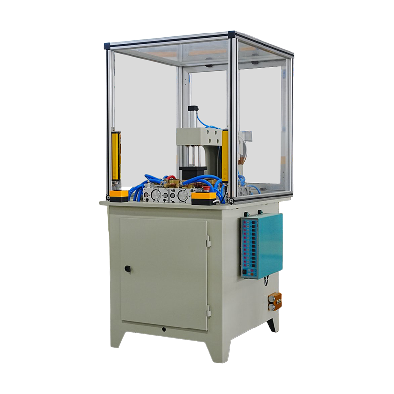
The Welding Machine for Box Bottom is designed for precise bottom‑plate welding of memo boxes. Featuring a stable welding unit and precise positioning fixtures, it ensures accurate alignment and consi...
See Details -
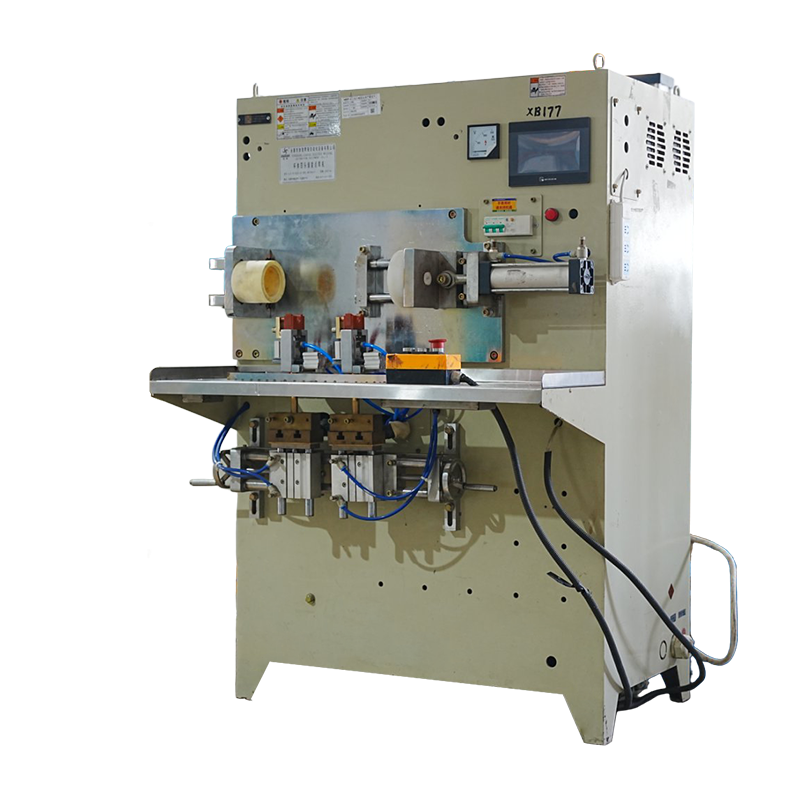
The 4‑Head Capacitor Discharge Welding Machine for Cup Bodies is a high‑precision automatic welding solution designed specifically for stainless‑steel insulated cup manufacturers.
See Details -
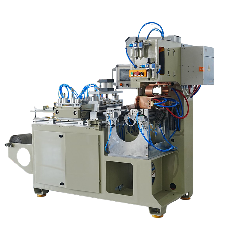
The Drum Roll Mesh Welding Integrated Machine combines drum body welds and wire mesh attachments in a single automated workflow, streamlining assembly processes for mesh‑reinforced drums or filtration...
See Details -
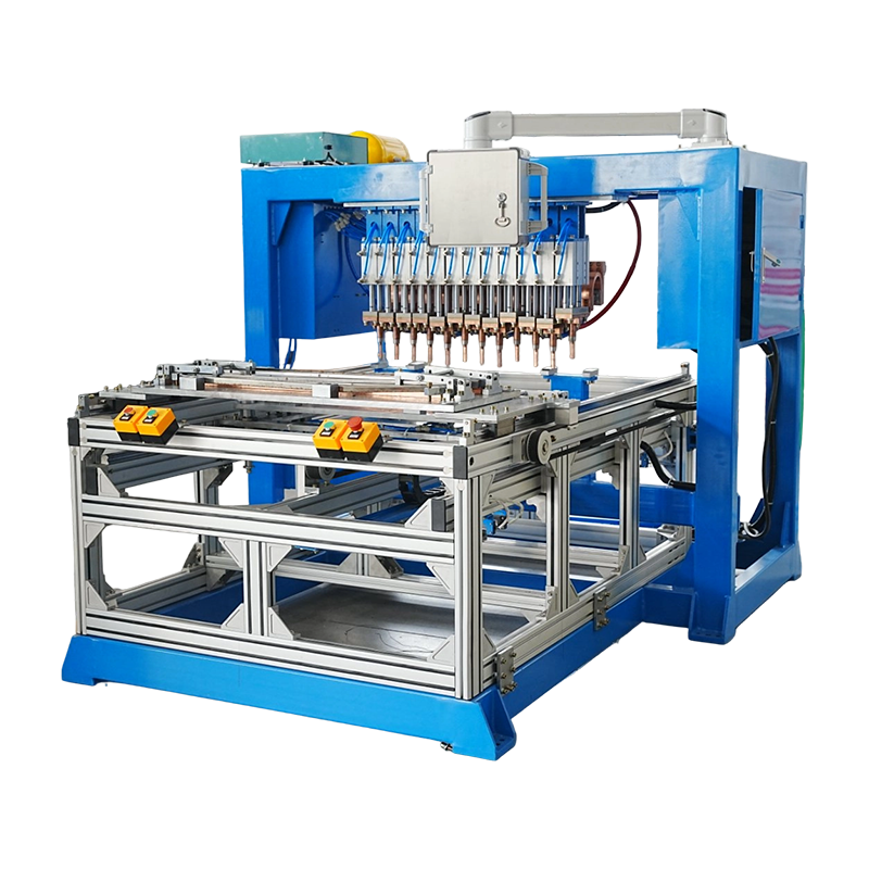
The Alternating Gantry Spot Welding Machine is an automated dual‑station resistance welding solution that maximizes productivity by enabling one station to weld while the other is being loaded or prep...
See Details -
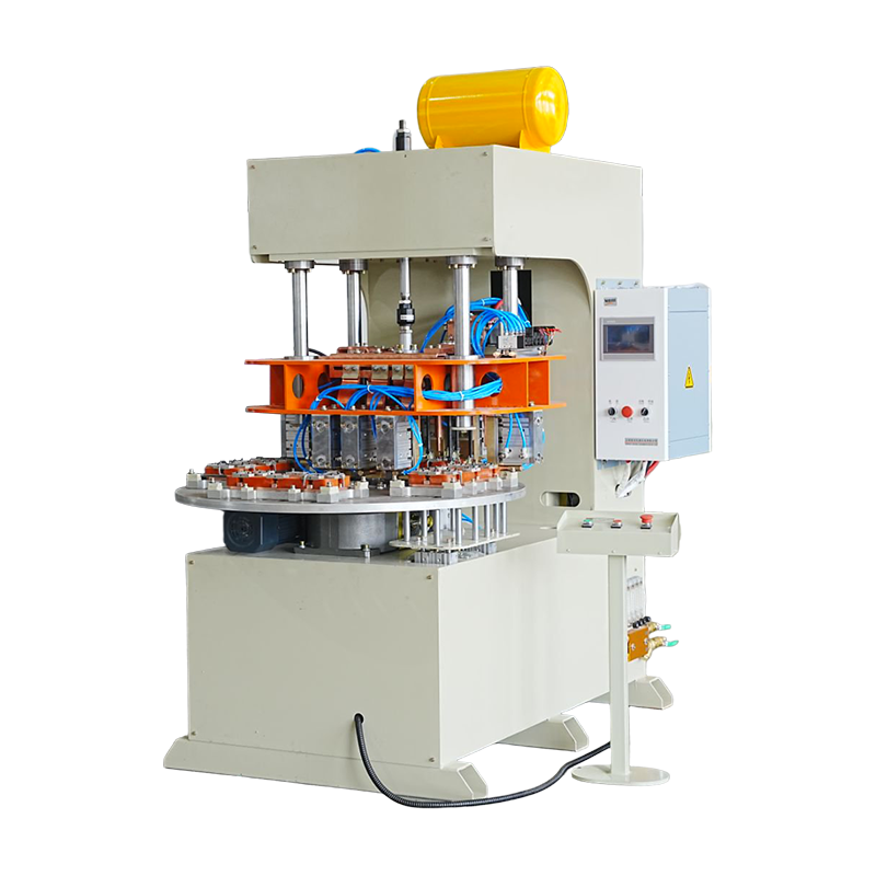
The Multi‑Head Welding Machine for Furnace Frames integrates several welding heads working in synchronized fashion to accomplish multiple joint welds in a single machine cycle.
See Details



 +86-15268688035
 jx12@4006796688.com
 NO.99,Huaxi Road,Chengxi New District,Yongkang city,Zhejiang China.
Message Us Right Now!
Copyright © Yongkang Jiaxiao Welding Automation Equipment Co., Ltd. All Rights
Reserved
China Welding Equipment Manufacturer
